Difference between revisions of "Assembling Zynthian Kit V5.1"
| Line 215: | Line 215: | ||
<br clear=all> | <br clear=all> | ||
| + | [[File:build51_rpi5_thermal_display_cable_bending_00.jpg|600px|right]] | ||
[[File:build51_rpi5_thermal_display_cable_bending_03.jpg|600px|right]] | [[File:build51_rpi5_thermal_display_cable_bending_03.jpg|600px|right]] | ||
[[File:build51_rpi5_thermal_display_cable_bending_01.jpg|600px|right]] | [[File:build51_rpi5_thermal_display_cable_bending_01.jpg|600px|right]] | ||
Revision as of 07:20, 16 September 2024
1 Previous Requirements
1.1 BOM V5.1 kit
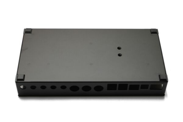
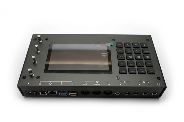
- V5.1 Aluminum Case
- Bottom
- Top
- Main Board
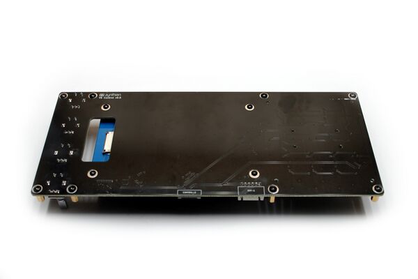
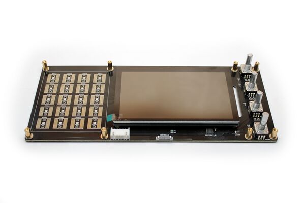
- Control Board
- Display
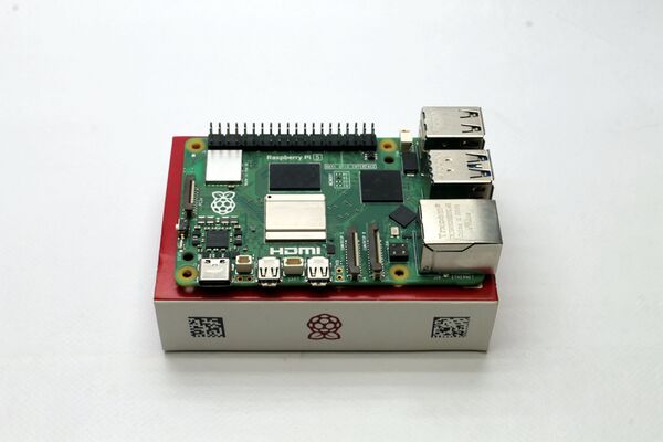
- Raspberry Pi5
- Thermal Block
- Thermal Pad (1 piece of 6 x 2 cm)
- Silicone Keypad
- Rubber Feet (4 units)
- Wiring
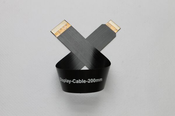
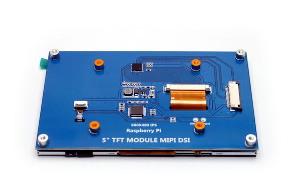
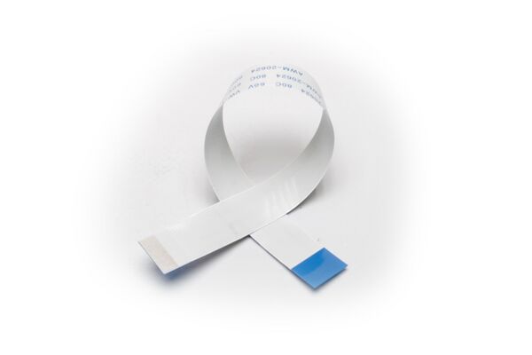
- RBPi5 DSI display flat cable: 20cm long, 1.6cm wide, 1mm/0.5mm pitch
- Control Board flat cable: 15cm long, 1cm wide, 0.5mm pitch
- USB-C adapter + flat cable: 5cm long, 1cm wide, 0.5mm pitch
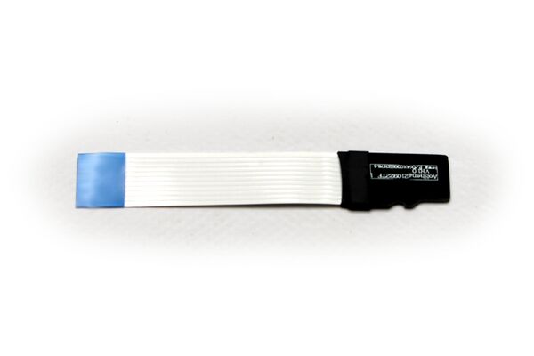
- uSD-card adapter with flat cable: 5cm long, 1cm wide, 1mm pitch
- Screws
- 12 x ISO7380 M2.5x5mm black zinc-plated steel (the smaller ones with round head)
- 21 x ISO7380 M3x5mm black zinc-plated steel (the slighty bigger ones with round head)
- 10 x DIN7991 M3x6mm black zinc-plated steel (the ones with conic head)
- 4 x DIN916 M3x4mm black zinc-plated steel (the headless ones)
- 8 x Hexagonal Spacer M3x10mm brass
- Mechanized Aluminum Knobs (4 units)
- Power Supply: 24V, 1.5 Amp (1 unit)
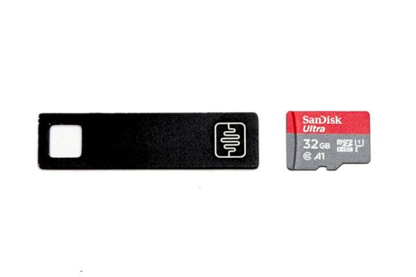
- SD-Card >= 32GB (NOT included in V5.1 kit)
- Optional: CR2032 lithium battery (NOT included in V5.1 kit)
WARNING!!
For working, the V5.1 needs a SD-card with the ZynthianOS software. Learn how to download the SD-image and prepare your SD-card.
1.2 Tools Required
- Allen Spanner 1.5 mm
- Allen Spanner 2.0 mm
- Scissors or Cutter (NOT included in V5 kit)
- Rule meter (NOT included in V5 kit)
1.3 Time Required
Depending on your skills and ability it may take 1 to 3 hours.
2 General Advice
- Read and follow carefully the assembling instructions. Don't ignore any guidance or recommendations. We are quite lazybones, so we should have had some important reason to write them.
- Use the browser's zoom to magnify the details in the pictures. They have good resolution and will allow you to see all details you need.
- Prepare the working space and the needed tools. A clean 120 x 60 cm table will be big enough. More is always welcome. Less is not recommended. Remove all stuff you don't need from the surface and prepare the tools you will need.
- Ensure you have good lighting in the working area. Having good lightning will ease delicate operations, especially those involving smaller parts.
- Please, be extremely delicate when manipulating the flat cable connectors (FPC). They are the weakest parts and can be easily broken. Look carefully at the photos/videos and proceed just in the way we recommend. Use 2 hands, one finger from each hand. Avoid manipulating the connectors with a single hand or finger and don't use any tool for this.
- Don't be impatient. If you have doubts or you don't know how to go on, please, stop assembling and ask in the forum or send an email to support@zynthian.org. It's better to wait some hours to get an answer than waiting for days/weeks to get a replacement part.
- Keep your hands clean so you can enjoy a nice unit after finishing.
WARNING!!
DON'T USE FORCE! NEVER! Some parts are really delicate, especially flat cable connectors (FPC), and you can easily break something if you are brute. Assembling the V5 unit is not difficult at all, but it's a clock-maker work. A beginners one that almost everyone can do, but clock-maker's task anyway. If you are not very used to manipulate this kind of stuff, please, proceed slowly. Thinking twice will let you build it once.
3 BOTTOM PART
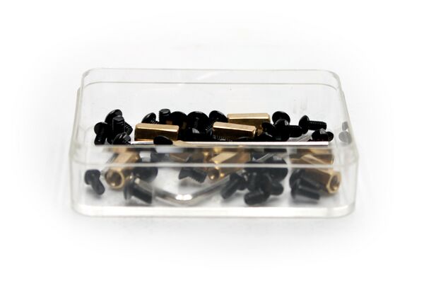
3.1 Dump the screws from the bag in a suitable receptacle
Be careful when opening the screws bag. Some of them are really small and you can easily lose them. Please, don't dump them on the table's surface or on top a piece of paper. We recommend to dump the bag's content in a small tray, so you can look at and take out the parts easily while getting them well confined so they can't be lost.
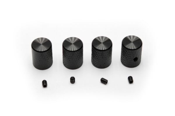
Pay special attention to the 4 tiny headless screws used to secure the knobs. They are really small!! You can screw them into the knobs as a first step to avoid losing them during the build process.
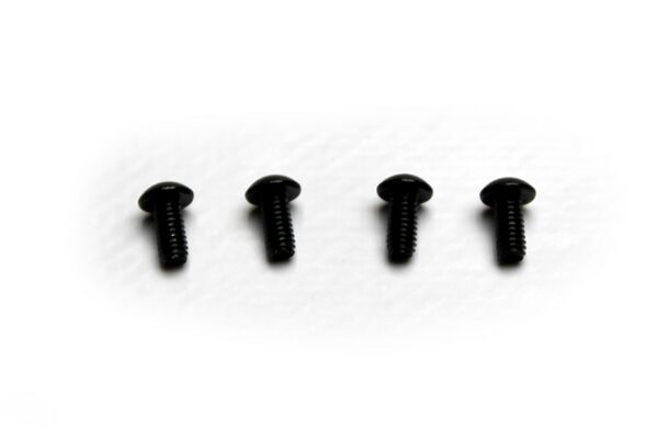
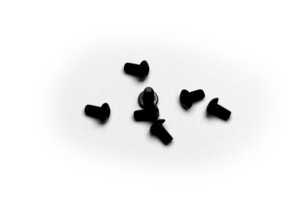
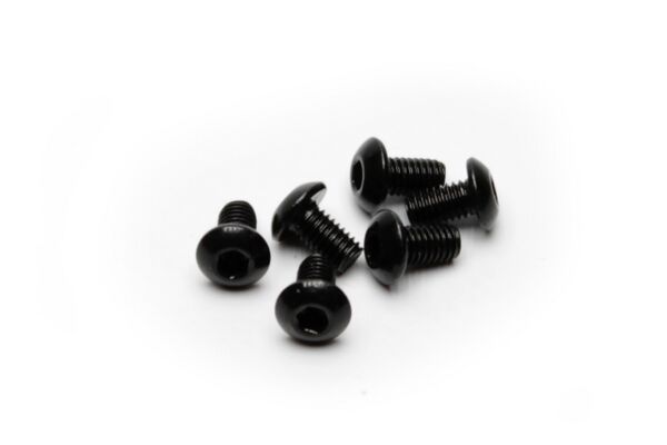
Now is a good time to familiarize yourself with the different screw models available. Take a close look at the content of the screws bag and try to identify:
- 12 x ISO7380 M2.5x5mm black zinc-plated steel => the smaller ones with round head
- 21 x ISO7380 M3x5mm black zinc-plated steel => the slighty bigger ones with round head
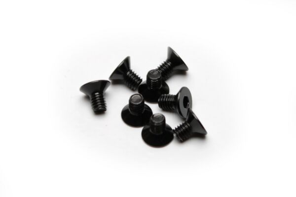
- 10 x DIN7991 M3x6mm black zinc-plated steel => the ones with cone-shaped head
- 4 x DIN916 M3x4mm black zinc-plated steel => the headless ones
- 8 x Hexagonal Spacer M3x10mm brass => they are the only brass parts
3.2 Stick the rubber feet to the aluminum case bottom
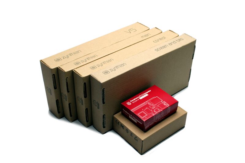
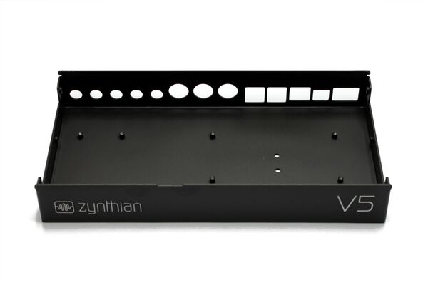
1. Look for the aluminum case bottom part in the "V5" case package:
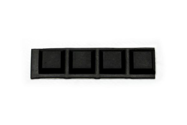
2. Look for the 4 x rubber feet inside the wiring bag, in the "Screen and Bits" case:
3. Stick the 4 x rubber feet to the aluminum case bottom part. This will prevent scratches during the assembly process.
3.3 Plug the display ribbon cable into the RPi4
1. Look for the display ribbon cable in the "Screen and Bits" case. It's 20cm long and 1.6cm wide:
2. Look for the RPi4 compute module in the "Accessories" case.
3. Open the RPi4's DSI connector by softly pulling both sides of the tiny black tongue at once. When it's totally open, push the ribbon cable inside, straight, with the blue side facing out. All flat cables in the V5 kit are reversible, so you can take any of the 2 caps, while taking care of placing the blue side facing out. When the cable is tightly inserted, close the connector by pushing the tongue with 2 fingers, one of each hand. Pay attention to ensure the cable does not move out of the connector. If it's not well inserted or not straight, repeat the operation until it's OK.
WARNING!!
When possible, use 2 hands to manipulate the fragile FPC connectors. You will control the applied force a lot better compared to just using a single hand. If you can't use both hands, take extreme care. Indeed, you should always take extreme care while manipulating FPC connectors.
Note:
If you break an FPC's connector tongue, you could work around the problem using a hot glue gun. Not nice, but it works quite well!
3.4 Install the thermal block
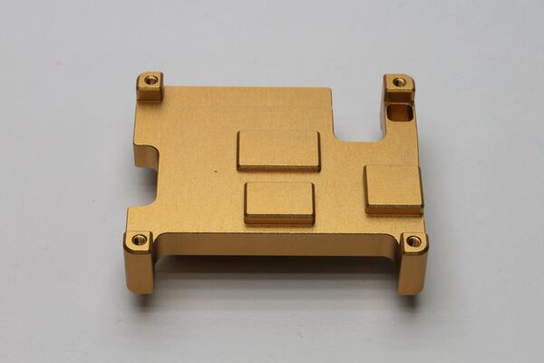
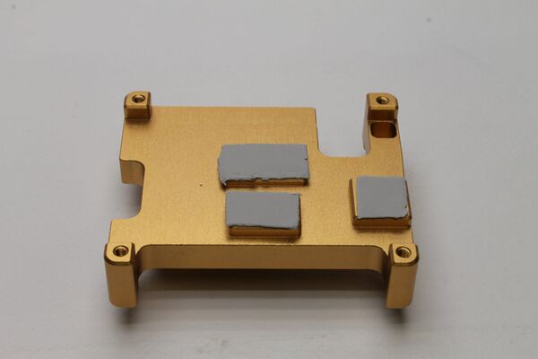
Zynthian V5.1 gets a 20% extra power from the RPi5 by overclocking the CPU up to 3 GHz. For this to work properly, we need to remove the heat generated by the RPi5's components. As we don't want a noisy fan, prone to failure, pushing dust inside our nice case, we are using the aluminum case as a huge heat-sink. This is achieved by the thermal block, a solid aluminum block that closely contacts with the RPi5's chips and serves as a heat-highway to the aluminum case bottom, and from there, to the rest of the aluminum case. When your zynthian V5.1 is working hard, or when external temperature is high enough, you will note the aluminum case getting hot. This is good because it means the thermal block is doing its job of transferring heat from the inside to the aluminum case body, where it's dissipated to the ambient environment.
Having understood all this, you may realize this is a key step for getting your V5.1 working at 100% of its capacity, so don't be in a hurry and take your time to do a good job. Let's start!
1. Look for the thermal block in the accessories case.
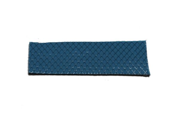
2. Look for the piece of thermal pad in the wiring bag, in the "Screen and Bits" case. It is a piece of approximate size of 60 x 20 mm, gray on one side and blue on the other.
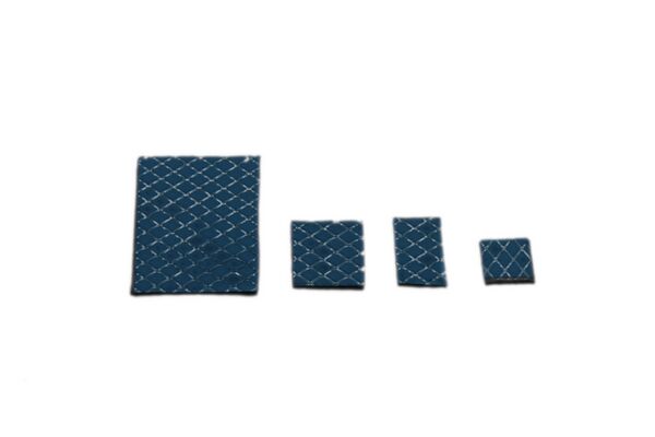
3. Using the rule-meter and the scissors or cutter, cut 4 little pieces of thermal pad with these apr sizes:
- 20 x 28 mm
- 19 x 12 mm => This is the most important!
- 14 x 9 mm
- 11 x 11 mm
4. Remove the blue protective sheet from the 3 smaller pieces and stick them to the inner side of the thermal block, the one that makes contact with the RPi5. You'll recognize it because it has 3 small rectangular islands that fit the size of the 3 smaller pieces you cut out. You can use your finger to stick it, pressing and extending the thermal pad. Use your fingernail to cut off the excess, if any.
5. Take 4 x ISO7380 M2.5 screws. They are the smaller ones with rounded head.
6. Remove the transparent protective sheet from the 3 pieces of thermal pad and fix the RBPi4 compute module to the thermal block using the 4 x ISO7380 M2.5 screws.
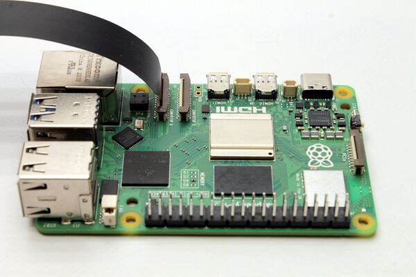
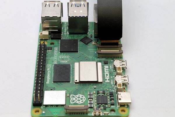
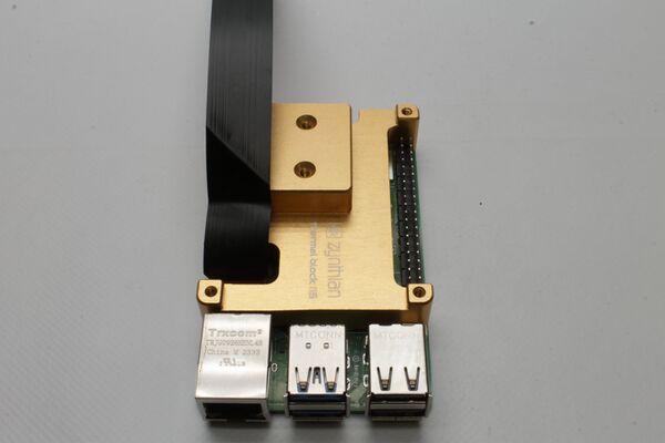
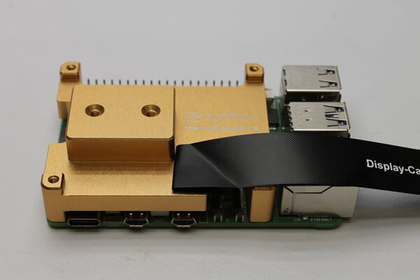
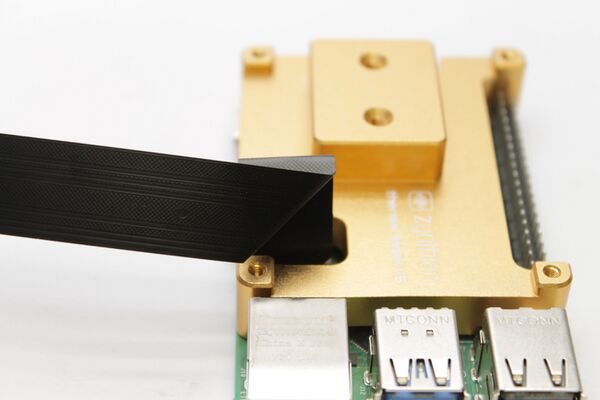
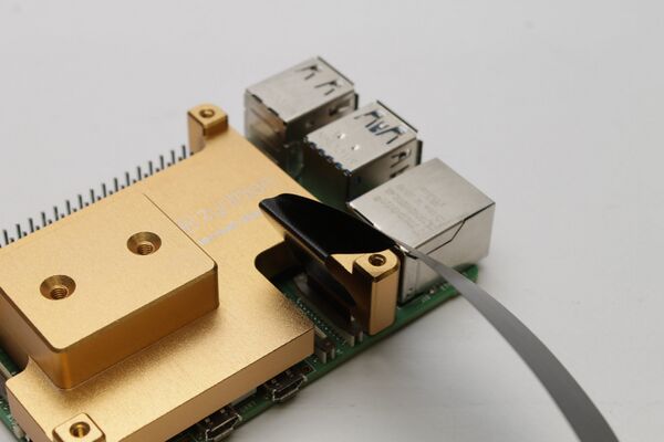
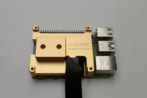
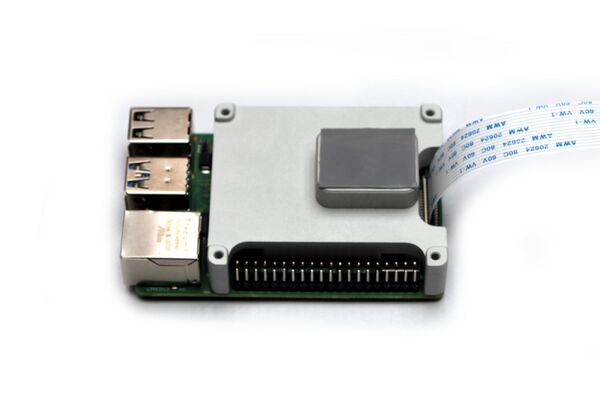
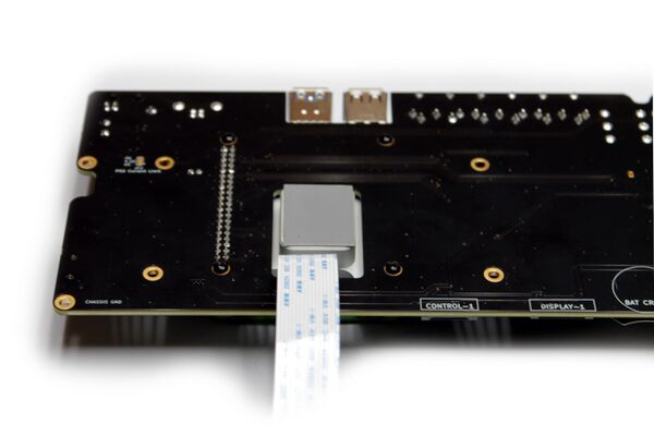
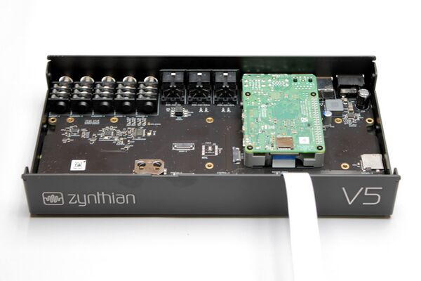
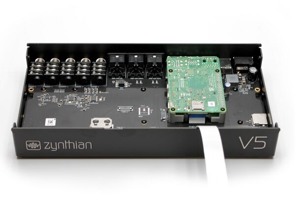
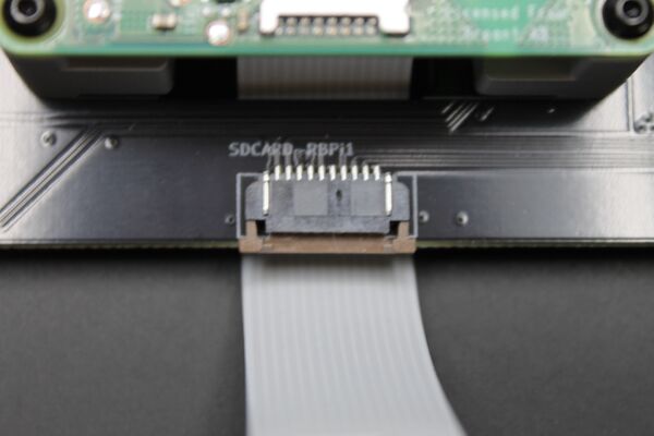
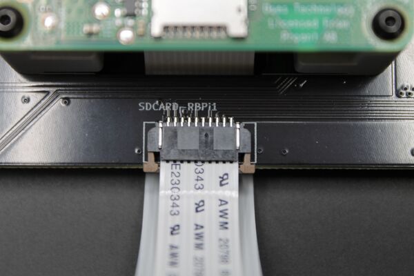
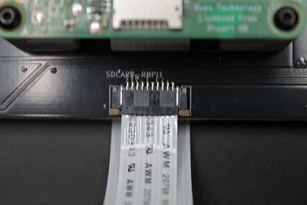
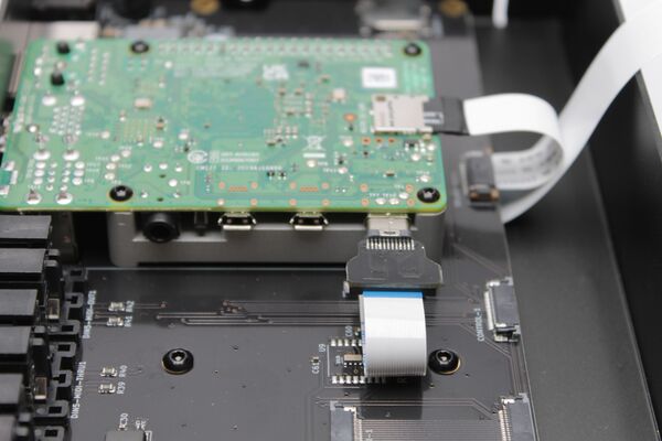
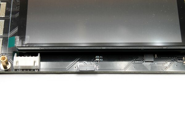
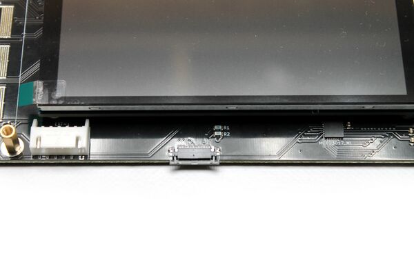
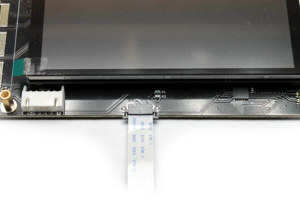
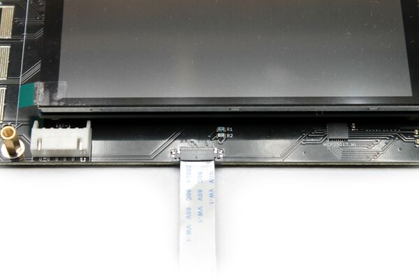
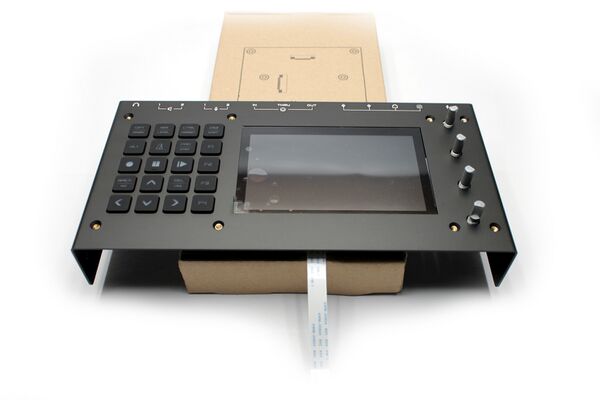
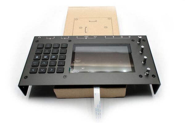
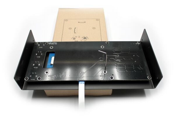
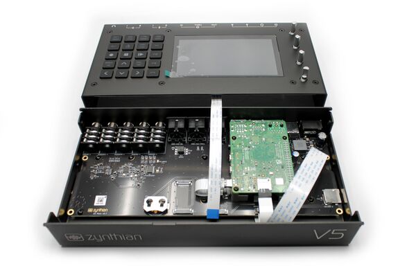
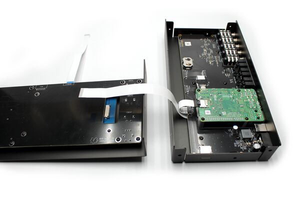
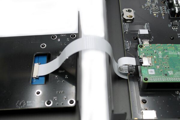
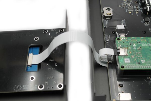
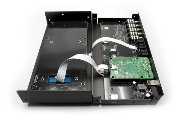
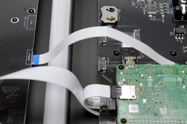
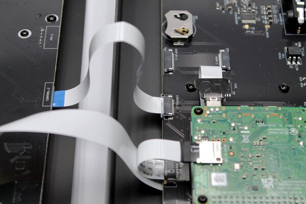
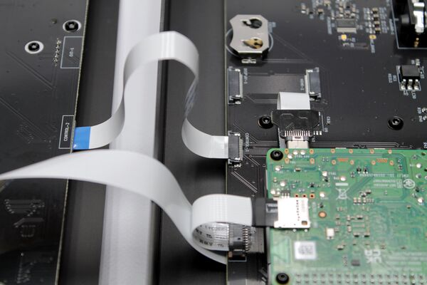
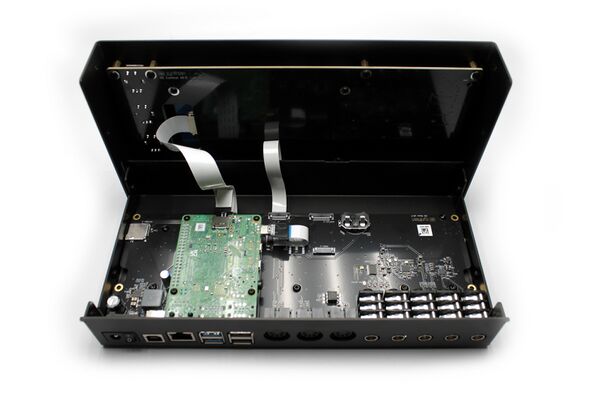
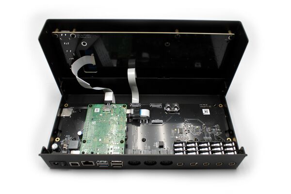
7. Before installing the "RPi5 + thermal block" assembly in the main board, you must fold the display cable adequately, so it goes in the right direction. You must fold it twice, putting attention to the pictures and using your "common sense". The first fold is straight and the second one is at 45º, so you get the cable going out the RPi5 with the text "Display-cable-200mm" on the down side. We show several pictures from different angles. Zoom in as needed until you have clear how to proceed. Take your time and think twice to do once.
8. Finally, stick the remaining piece of thermal pad (27 x 20 mm) on the contact surface in the external side of the thermal block. That is, on top of the "tower" with 2 tiny holes. Follow the same procedure you already did with the 3 smaller pieces, but don't remove the transparent protective sheet yet. This will be done later, when installing the module in the aluminum case bottom.
3.5 Assemble the Main Board into the aluminum case bottom
1. Take the main board from its case.
2. Take 4 x ISO7380 M2.5 screws. They are the smaller ones with rounded head.
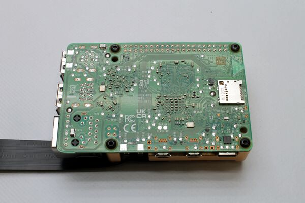
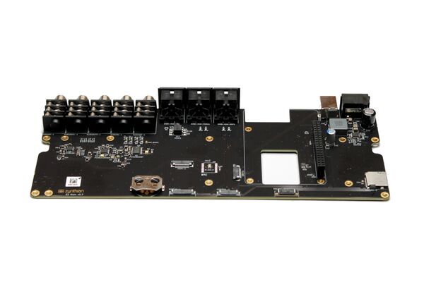
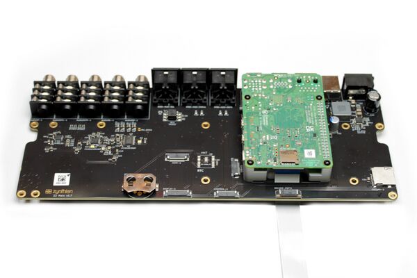
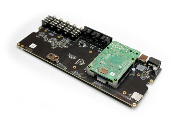
3. Plug the RBPi4 (with the thermal block attached) on the Main Board's RBPi4 socket, the big one with 2 rows of 20 pin-holes each. Pay attention to not bend any pins. Also note that the display flat cable should pass through the rectangular hole in the main board, as seen in the photos (zoom in if you have doubts).
4. Fix the thermal block to the main board from the backside using the 4 x M2.5 screws.
Note:
At this point, you can do these steps in advance: 3.6 and 3.7. Some people will find it more comfortable to plug in the SD-card & USB-C adaptors before assembling the main board in the aluminum case. It's up to you!
5. Take 7 x ISO7380 M3 screws. They are the mid-size ones with rounded head.
6. Remove the transparent protective sheet from the piece of thermal pad stuck to the thermal block bottom and softly place the main board in the aluminum case bottom. You will find it more comfortable to grab the thermal block to do this operation. Fix it using the 7 x ISO7380 M3 screws.
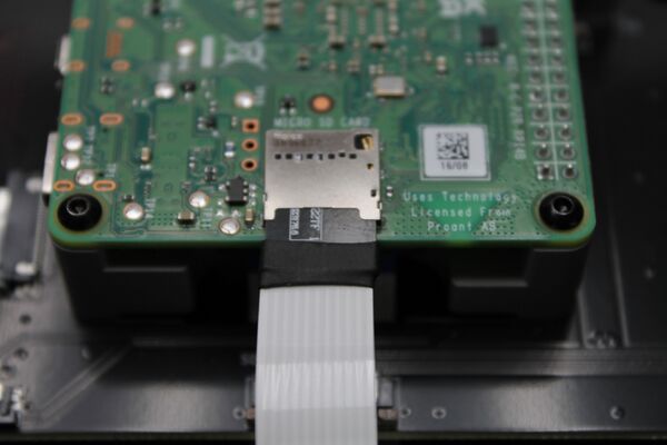
3.6 Plug SD-card adapter
1. Look for the SD-card adapter in the wiring bag.
2. Carefully, using 2 fingers, one on each hand, pull the main board's SD-card connector tongue until it's totally open.
3. Insert the SD-card adapter's ribbon cable. It must be inserted straight, with the blue side facing down.
4. When it's totally inserted, push the tongue with 2 fingers at once and close the connector. Pay attention to ensure the cable does not move out of the connector. If it's not well inserted or not straight, repeat the operation until it's OK.
4. Plug the SD-card adapter into the RPI4's SD-card holder.
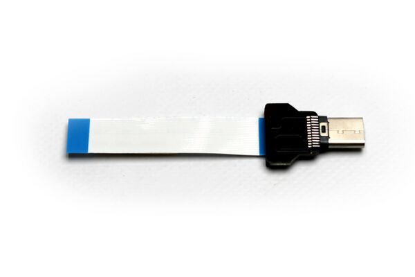
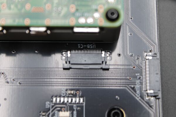
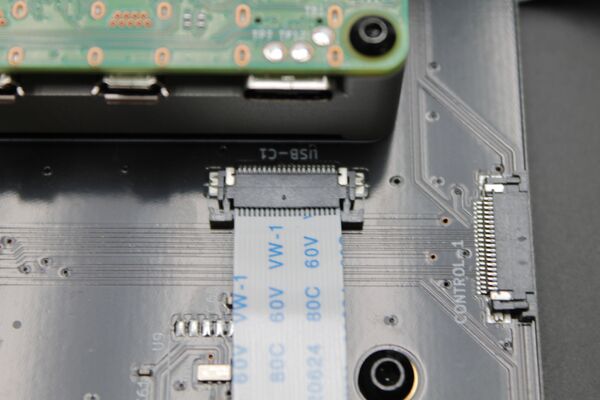
3.7 Plug USB-C adapter
1. Look for the USB-C adapter in the wiring bag.
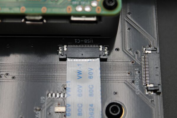
2. Carefully, using 2 fingers, one on each hand, pull the main board's USB-C connector tongue until it's totally open.
3. Insert the USB-C adapter's ribbon cable. It must be inserted straight, with the blue side facing down.
4. When it's totally inserted, push the tongue with 2 fingers at once and close the connector. Pay attention to ensure the cable does not move out of the connector. If it's not well inserted or not straight, repeat the operation until it's OK.
5. Plug the USB-C connector into the RPI4's USB-C socket.
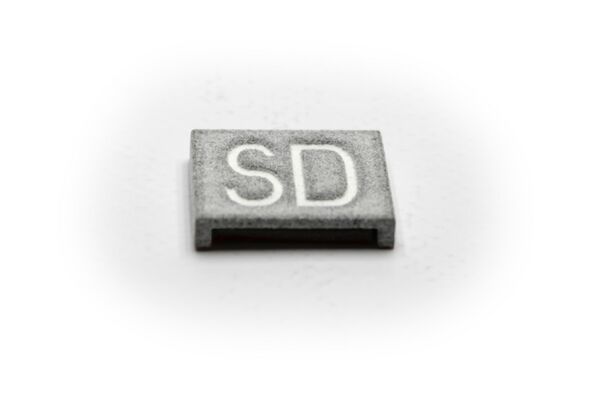
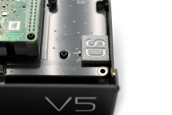
3.8 Stick the SD-card holder cover
This little piece of plastic is just to make sure you can't accidentally push the SD card into the gap between its slot and the case, thus losing it. But ... can this happen? Well, it's not easy, but we provided this nice piece of plastic for a reason ;-)
1. Look for the SD-card holder cover in the wiring bag.
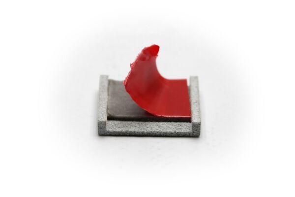
2. Remove the protective sheet.
3. Stick it on the main board's SD-card holder, so it is well-adjusted, touching the aluminum case.
3.9 Secure the thermal block to the aluminum case bottom
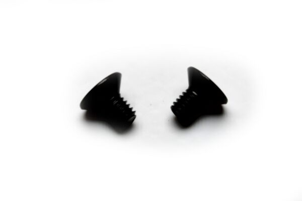
1. Look for 2 x DIN7991 M3 screws. They have countersunk flat heads.
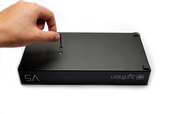
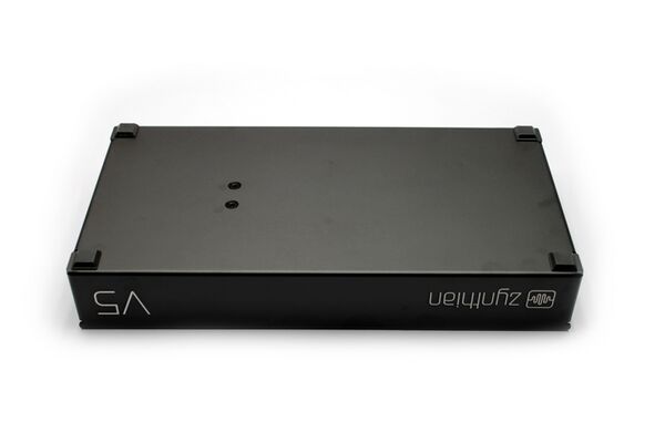
2. Flip the aluminum case bottom and look for the 2 countersunk holes. Using the Allen wrench, punch the thermal pad through the holes.
3. Screw the 2 bolts and tighten them well enough, but not too much.
4 TOP PART
4.1 Secure the top-spacers on the control board
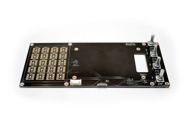
1. Take the control board from its case. You don't need the silicone buttons yet.
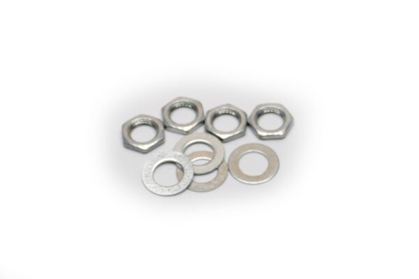
2. If you don't want your Zynthian V5 to behave like a rattle, please, remove the nuts and rings from the rotary encoders. You don't need these, so you can throw them away or keep them in the screws tray.
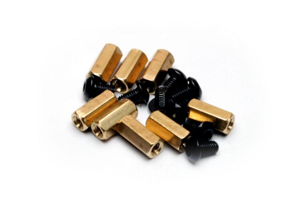
3. Take the 8 x brass spacers 10mm and 8 x ISO7380 M3 screws (the mid-size ones with round head).
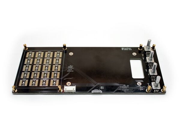
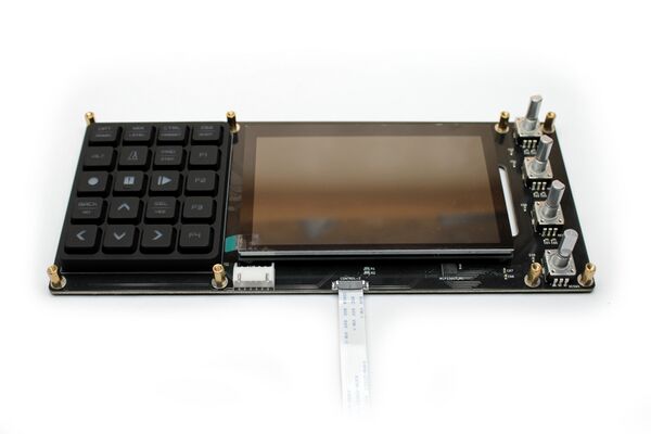
4. Secure the 8 x spacers on the control board's top side. To do this, insert the bolt from the back side and while holding it with your finger, fasten the spacer with the other hand until it's tight. You don't need a wrench for this, but you can use one if you like.
4.2 Assemble the display on the control board
1. Take the display from its case. It should have 2 protective sheets. The first one is thin and baggy and the second one is thicker and it fits the LCD panel except for a small green tab. Remove the first protective sheet (the thin and baggy one) and leave the second one untouched. After this, flip the display and remove the 4 yellow protective sheets from the outer spacers. You can use your fingernail or a cutter for this operation.
2. Take 4 x ISO7380 M2.5 screws (the smaller ones with round heads).
3. Secure the display to the control board's top side using the 4 x small M2.5 screws. Don't tighten these bolts yet!!! The display must be loose to get a good fit with the aluminum case top part. You will tighten these screws later. Pay attention to the display orientation. The display FPC connector for the flat cable must be accessible through the main board's square hole.
4.3 Plug the flat ribbon cable into the control board
1. Look for the control flat ribbon cable in the wiring bag. It's grey with blue tips, 15cm long and 1cm wide.
2. Carefully, using 2 fingers, one on each hand, pull the control board's FPC connector tongue until it's totally open.
3. Insert the ribbon cable into the FPC connector. It must be inserted straight, with the blue side facing down. All flat cables in the V5 kit are reversible, so you can take any of the 2 caps, while taking care of placing the blue side facing down.
4. When it's totally inserted, push the tongue with 2 fingers at once and close the connector. Pay attention to ensure the cable does not move out of the connector. If it's not well inserted or not straight, repeat the operation until it's OK.
4.4 Secure the control board, silicone buttons and display to the aluminum case top
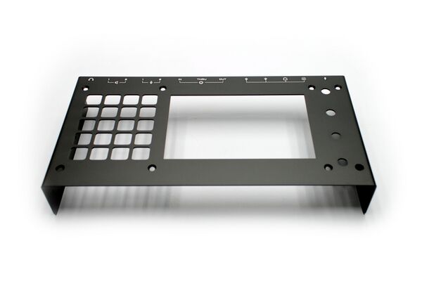
1. Look for the aluminum case top part.
2. Look for 8 x DIN7991 M3 screws. They have countersunk flat heads.
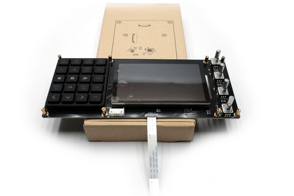
3. Place the silicone button pad on top the control board. Note the tiny silicone studs in the bottom of the pad and pay attention to make them fit into the small positioning holes on the control board. Once it's done, softly push the button pad to the side to check whether it sits snug in it's place. The pad shouldn't move when you try pushing it to the side.
4. Use the "Screens & Bits" case as a mounting stand and place the control board on it, as shown in the picture.
5. Place the aluminum case top part over the control board taking care of orientation and proceeding slowly. It's a good time to remove the display's protective sheet, or at least, fold the green tab out of the way so the display makes a good fit into the case's window.
6. Secure the control board with the 8 x M3 countersunk screws. Again, tighten enough, but not too much.
7. Flip the top part and place it over the carton-stand again. Now is the right moment to tight the 4 display screws from step 4.2 (do you remember?).
8. Congratulations! We are ready to join everything together.
5 JOINING BOTH PARTS AND CLOSING THE CASE
If you want to place a CR2032 lithium battery for the RTC (Real Time Clock), this is a good moment. If not, don't worry, you can open the case and do it later.
5.1 Plug the display flat cable into the display
1. Place the two parts one aside the other, forming 90º angle, as shown in the picture.
2. Using two fingers, one on each hand, softly pull the display's FPC tongue until it's open. Insert the flat ribbon cable coming from the RPi4 into the bottom's part. Do it straight, without bending or twisting it in any way, so the blue side is face down.
3. When it's totally inserted, softly push the tongue using 2 fingers, one on each hand, until it's totally closed. Pay attention to ensure the cable does not move out of the connector. If it's not well inserted or not straight, repeat the operation until it's OK.
5.2 Plug the control flat cable into the main board
1. Rotate the top part until it's parallel to the bottom part, as shown in the picture.
2. Using two fingers, one on each hand, softly pull the main board's control-1 connector tongue until it's open. Insert the flat ribbon cable coming from the control board (top part). Do it straight, without bending or twisting it in any way, so the blue side is face down.
3. When it's totally inserted, softly push the tongue using 2 fingers, one on each hand, until it's totally closed. Pay attention to ensure the cable does not move out of the connector. If it's not well inserted or not straight, repeat the operation until it's OK.
5.3 Close the aluminum case
1. Fit the upper part into the lower part forming a 90º angle, as shown in the picture.
2. Note the way the display flat cable naturally bends. You should force this bending by pressing with your fingers and marking a 45º fold. Zoom into the picture to see the detail.
3. Close the case slowly, taking care that the cables are not being trapped.
4. Before securing the case top and the knobs, it's a good time to burn a SD-card with the latest zynthian software image and check everything is working OK. Please, use a good quality SD-card and follow the instructions carefully.
First boot could take some time. Don't be impatient and wait until you see the splash screen with the logo. If the display remains black after 1 minute, please, re-check the instructions and re-burn the SD-card again. If this still don't work, try with a different SD-card before reporting in the forum. For solving SD-card issues, it could be useful to check the RPi4 status LEDs.
Once you see the splash screen, it could take some minutes until the system is ready. You deserve a beer, or at less some some tea or coffee. When the first-boot process finishes, the zynthian will reboot and you will be in the main menu, ready to play.
5. If everything worked fine and your zynthian booted, finish the task before start exploring your new zynthian V5. Take the remaining 6 x ISO7380 M3 screws and secure the case, 3 on each side. Tighten enough, but not too much.
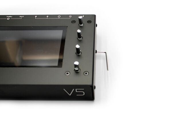
5.4 Attach and secure the knobs
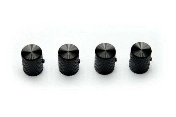
1. Take the 4 x mechanized aluminum knobs from the wiring bag and the 4 x super-tiny DIN916 M3 screws (headless screws).
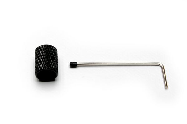
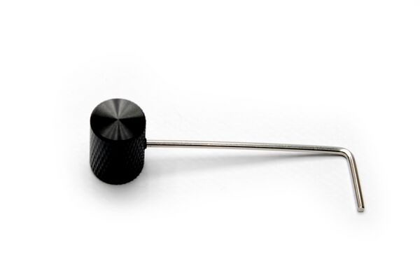
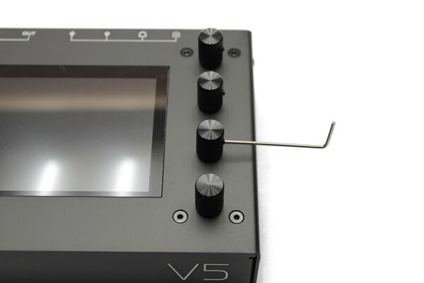
2. Insert the headless screw in the allen wrench and screw it partially into the knob side hole, until its head is slightly over the knob side.
3. Repeat the step for the 4 knobs.
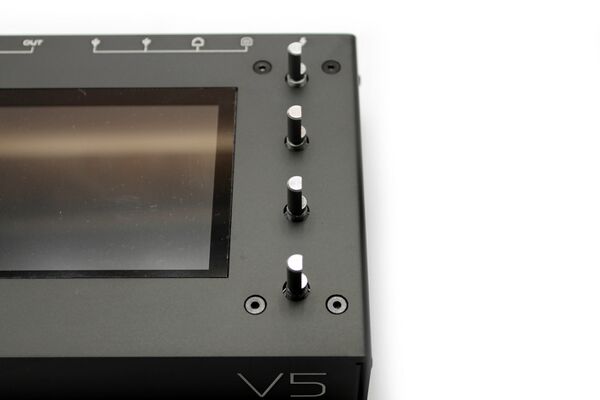
4. Turn the 4 x rotary encoders until the flat cotter is pointing outside.
5. Tighten the headless screws. Enough but not too much.
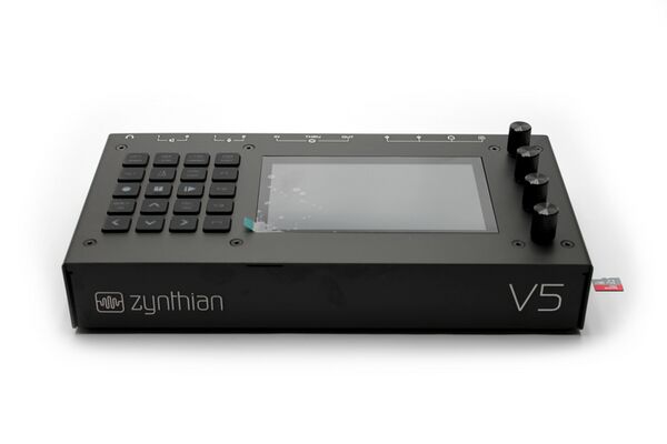
6. Congratulations! Your Zynthian V5 is ready to boot for the first (or second??) time. If you didn't yet, it's time to burn a SD-card with the latest zynthian software image. Please, use a good quality SD-card and follow the instructions carefully.
First boot could take some time. Don't be impatient and wait until you see the splash screen with the logo. If the display remains black after 1 minute, please, re-check the instructions and re-burn the SD-card again. If this still don't work, try with a different SD-card before reporting in the forum. For solving SD-card issues, it could be useful to check the RPi4 status LEDs.
Once you see the splash screen, it could take some minutes until the system is ready. You deserve a beer, or at less some tea or coffee. When the first-boot process finishes, the zynthian will reboot and you will be in the main menu, ready to play.
It's time to take a look to the user's guide!
