Zynthian Hardware
1 Zynthian hardware
If you want to explore creating a DIY Zynthian install with various custom hardware, you will find more info here.
- For the most hassle free experience a full kit is recommended as it is well documented and supported and comes with a full set of instructions for assembly
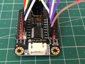
- If you want to build a custom kit with minimal or no soldering, that's possible by finding port expanders, buttons and encoders on PCBs with built-in pins
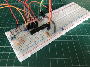
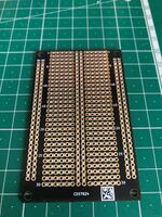
- If you are comfortable with a soldering iron, you can create a more robust and reliable control interface (with more choices for parts) arranged on a prototype board
2 The official Zynthian kit
As of late 2024 the kit version is v5.1 (which supports Raspberry Pi 5), it can be purchased by visiting the Zynthian shop. You can also purchase some individual parts if you want to build a custom version that will better fit your needs.
As is, the kit consists of:
- a Raspberry Pi 5 (Raspberry Pi 4, 3 and 3B+ are also supported. Raspi 4 or higher is recommended as Raspi 3 is less capable running multiple sound engines simultaneously). The kit can be purchased with or without the Raspberry Pi if you already have one lying around.
- an high end sound card, the Hifiberry DAC+ADC stage which offers Burr Brown Texas Instruments DAC (TRS 6.35mm jack stereo line out) + ADC (TRS 6.35mm jack stereo line in)
- a dedicated 3.5 inch touchscreen display which also has a port expander on board for connecting the
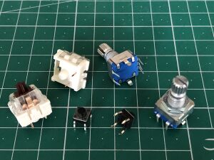
- 4 rotary encoders for controlling the user interface (UI)
- and the 4 assignable push buttons
- an expansion board called Zynaptik that provides the MIDI interface (IN, OUT and THRU) and some footprints for components that are not populated: a second port expander for adding more switches and/or rotary encoders, an ADC and a DAC footprints for adding CV gates.
- a lovely but strong metal case
- all the needed wires with their already mounted connectors
Building an official kit is quite easy, the procedure is fully described here.
You will also need, and this is really important for having the best experience:
- A good quality SD Card of at least 16Gb
- a good Power Supply Unit (PSU) (5V 3A)
- a strong USB powering cable
Official Raspberry Pi PSU is highly recommended (can deliver 5.1V 3A and is shipped with an excellent USB cable) and is also available in the shop.
3 Compatible hardware
The Zynthian web configuration tool has several options to adapt the system to different kind of hardware. Be aware that only the kit parts are officially supported, others have been reported to work at a given time but could not work anymore.
3.1 Displays
Below is the list of the hardware that can be configured with the Webconf tool and the kind of interface they use. This list is certainly out of date, for an up to date list, refer to the HARDWARE > Displays menu within the Webconf interface of your Zynthian install.
- PiScreen 3.5 (v2) GPIO-only
- PiScreen 3.5 (v1) GPIO-only
- PiTFT 2.8 Resistive GPIO-only
- PiTFT 2.8 Capacitive GPIO-only
- PiTFT 3.5 Resistive GPIO-only
- RPi-Display 2.8 GPIO-only
- WaveShare 3.2B GPIO-only
- WaveShare 3.2C GPIO-only
- WaveShare 3.5A GPIO-only
- WaveShare 3.5B GPIO-only
- WaveShare 3.5B V2 GPIO-only
- WaveShare 4A GPIO-only
- WaveShare 4C GPIO-only
- WaveShare 4 HDMI+GPIO
- WaveShare 4.3 HDMI+GPIO
- WaveShare 5 HDMI+GPIO
- WaveShare 5 HDMI+USB
- WaveShare 7 HDMI+GPIO 1024x600
- WaveShare 7 HDMI+GPIO 800x480
- WaveShare 7 HDMI+USB
- Sainsmart 1.8 GPIO-only
- MHS35 480x320 GPIO-only
- MPI5008 800x480 HDMI+GPIO
- Pi 7 Touchscreen Display 800x480 DSI+GPIO
- 5 inch DSI Display 800x480 DSI-only
- Generic HDMI Display
- Generic 4k HDMI Display
3.2 Audio interface
- HifiBerry DAC+ ADC PRO
- HifiBerry DAC+ ADC
- HifiBerry DAC+ light
- HifiBerry DAC+ RTC
- HifiBerry Digi
- HifiBerry Amp
- AudioInjector
- AudioInjector Isolated
- AudioInjector Ultra
- IQAudio DAC
- IQAudio DAC+
- IQAudio Digi
- PiSound
- JustBoom DAC
- JustBoom Digi
- Fe-Pi Audio
- Generic USB device
- Behringer UCA222
- Behringer UMC404HD
- Behringer UMC1820
- Steinberg UR22 MKII
- Edirol UA1-EX
- Yeti Microphone
- RBPi Headphones
- RBPi HDMI
Note: most of the USB sound cards should work out of the box with the "Generic USB device" settings.
4 Other hardware
4.1 Before you go for it - A note on random Chinese parts ordered online
Note: You are on your own when trying to make them work with Zynthian. Some can be well supported by Zynthian software as they are clones from some well knowns products, some will work with more or less hassles and some will just not work at all.
Advice: Be careful when trying to use any kind of "installer script" as they can override a Zynthian configuration file. It is always a good idea to test these kind of hardware on a stock Raspberry Pi OS and to study what's already done by the installer script.
4.2 Displays and interfaces
Many of them are Waveshare clones, look at them carefully and especially to the GPIO pins they use and to the chips used to control the display and the touch interface. Avoid displays that are using parallel, RGB or DPI interface.
- Above, a list of displays that should be supported by ZynthianOS is given, there are also a plenty of "no name" Chinese displays. If this is the you're planning to use, be careful when using a SPI display that pin number 12 (GPIO18) isn't used by your display for "backlight" or "led" control as this pin is needed by any DAC board on market. Of course, using an HDMI or DSI display or an USB sound card or the internal headphone will makes this remark useless ...
Upon spending some time looking at various Raspberry Pi compatible screens it will become clear the most typical connections are either DSI or HDMI+USB.
4.2.1 HDMI+USB Interface
These appear to be the most commonly available and at the time of writing generally cheaper than DSI.
Downsides These displays will likely take up more space when you try to mount one inside your chosen case. The touch interface also requires a USB port which is one less for your midi controllers or keyboard & mouse
Upsides There are more options and types of screens available with this interface (narrow bezel)
4.2.2 DSI - Display Serial Interface
The benefit of this interface for your DIY Zynthian is the compact flat cables for connecting the display that will leave
Downsides At the time of writing there were no narrow bezel screens available from waveshare using DSI
Upsides Simplified cable setup. Doesn't require any USB ports
Roundup of 10 Raspberry Pi compabtible displays here:
4.3 Audio Boards
Try to identify the DAC, ADC or CODEC chip
- with pcm5102, pcm5102a or es9023 chips, boards should be supported as hifiberry-dac light.
- With a pcm5122 chip boards should be supported as IQaudio DAC.
- With SGTL5000 Fe-Pi audio board should be compatible.
5 I/O hardware connections
Depending on the hardware used for your custom Zynthian, you may have a number of spare GPIO pins available that can be used to connect rotary encoders or buttons. These can then be assigned numbers in the Webconf wiring page to make them usable in Zynthian.
5.1 Direct to Raspberry Pi GPIO
See this thread for discussion on making connections to the Pi: Encoders directly to the GPIO of the Pi 4?
5.2 Via MCP23017 Port Expander
5.3 Port expander & rotary encoders
- The MCP23017 port expander can be found as SMD component mounted on a small breakout board. No bad experiences have been reported with them.
- You may find some rotary encoders already mounted on a small PCB: they do not fit to the schematic (have some pull up resistors and need to be powered) and bring usually many hassles.
5.4 Controls: Rotary encoders
- The MCP23017 port expander isn't really mandatory. You can choose to go with just the touch interface and there's nothing more to talk about or you can use an HDMI or DSI display. In that case, you will free up enough Rbpi GPIOs to wire the encoders directly to the Pi GPIOs (3 GPIOs per encoder). This setup could be configured through the webconf tool and is explained here.
- When using a self made MCP23017 setup, you can use any free GPIO you want for INTA and INTB interrupts as they are configurable through the webconf tool.
5.5 The MIDI interface
5.6 The audio side
6 Custom Cases
There is a collection of information about custom cases including guides, descriptions and files available at the github project for creating your own case with a 3d printer and other methods.
To see a huge collection of cases built by Zynthian users, see the Success Cases thread in the forum.
7 A deeper look at Zynthian Hardware architecture
7.1 Foreword
The following is based on the kit v4.1 schematics but keep in mind that most of it is optional ! One may choose to run an headless Zynthian, or with just a HDMI display and an USB and/or keyboard. Zynthian is modular enough to fits many needs a from pocket sized gear to a customized midi keyboard that will embed your build. All schematics below are from the V4.1 Kit Building Tutorial and can also be found on Github.
7.2 The Raspberry Pi
The Raspberry Pi is the heart of Zynthian, it runs the all the software and can be used "as is" in a headless setup. But it also communicates with all the hardware add-ons that makes a Zynthian Box.
The V4.1 setup use the following pins of your Raspberry Pi:
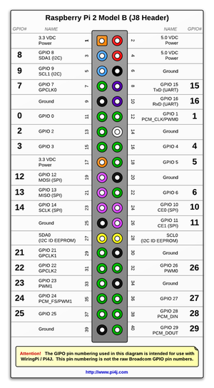
- Pins numbers 3 and 5: for the I2C protocol. I2C is used by the MCP23017 port expander and for controlling the Audio sound card.
- Pins numbers 8 and 10: for the serial interface (UART). This is for MIDI IN and OUT
- Pins numbers 12, 35, 38 40: for the I2S (or PCM as on the image) digital audio interface. Where pin 40 is for the output signal to the DAC (Digital to Analog Converter) and pin 38 is for the input signal drom the ADC (Analog to Digital Converter) which are both provided by the Hifiberry ADC+DAC stage soundcard.
- Pins 19, 21, 23, 26, 26 (SPI interface) and pins 11, 15, 18, 22 for the display and its touch interface.
- Pins 7 and 13: these are used for providing interrupts to the MCP23017 port expander.
- Power pins, 5V, 3.3V and GND are also used for powering the different components
Pin numbers given above are the Raspberry pins numbers and as noticed on picture and because Zynthian software makes the use of the WiringPi library, they have also a specific WiringPi number which does not correspond to the Broadcom chip pin number. So one may find useful to have this table:
| WiringPi GPIO | BCM pin | RBPI pin | RBPI pin | BCM pin | WiringPi GPIO |
|---|---|---|---|---|---|
| 3.3V | 1 | 2 | 5V | ||
| 8 | 2 | 3 | 4 | 5V | |
| 9 | 3 | 5 | 6 | GND | |
| 7 | 4 | 7 | 8 | 14 | 15 |
| GND | 9 | 10 | 15 | 16 | |
| 0 | 17 | 11 | 12 | 18 | 1 |
| 2 | 27 | 13 | 14 | GND | |
| 3 | 22 | 15 | 16 | 23 | 4 |
| 3.3V | 17 | 18 | 24 | 5 | |
| 12 | 10 | 19 | 20 | GND | |
| 13 | 9 | 21 | 22 | 25 | 6 |
| 14 | 11 | 23 | 24 | 8 | 10 |
| GND | 25 | 26 | 7 | 11 | |
| 30 | ID_SD | 27 | 28 | ID_SC | 31 |
| 21 | 5 | 29 | 30 | GND | |
| 22 | 6 | 31 | 32 | 12 | 26 |
| 23 | 13 | 33 | 34 | GND | |
| 24 | 19 | 35 | 36 | 16 | 27 |
| 25 | 26 | 37 | 38 | 20 | 28 |
| GND | 39 | 40 | 21 | 29 |
7.3 The display
7.3.1 Zynscreen v1.5
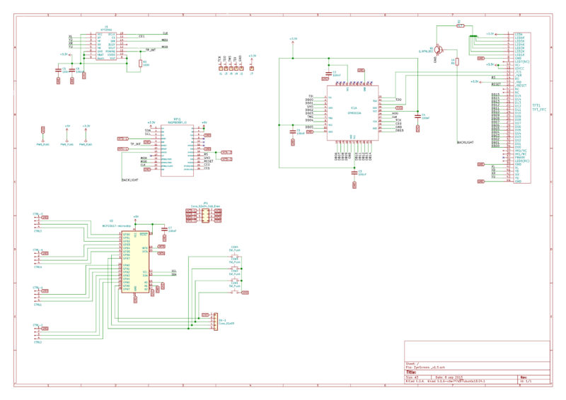
It's a Zynthian dedicated piece of hardware. The schematics above shows the PCB wiring.
- On the top right, the TFT1 connector to the LCD panel itself. RS, RESET and BACKLIGHT are directly connected to the RBPI. From DB00 to DB15 lines labels are connected to the IC1A chip while XL, YD, XR, YU labels are for the touch capability managed by the U1 IC.
- IC1A: Intel's EPM3032A Complex Programmable Logic Device (CPLD) which converts data coming from the SPI Bus to something understandable by the LCD panel. Don't ask, the manufacturer of the Zynscreen doesn't share the code for programming the chip by your own. Each LCD display will require its self microcode ... MOSI, CLK, CE0 are the SPI lines coming from the Rbpi while TCK, TDO, TMS, TDI goes to pads that are used by the manufacturer for programming the CPLD.
- U1 the "famous" XPT2046 touch interface IC. That one is very common. It use the Rbpi SPI interface, MOSI, MISO, CLK, CE1 plus a touch point interrupt TP_INT that is wired to Rbpi GPIO17 (pin number 11).
- U2, the MCP23017 port expander. It communicates to the Rbpi through the I2C protocol, using SDA and SCL pins (number 3 and 5) and creates two bank of eight GPIOs (GPA0-7 and GPB0-7). Each bank needs an interrupt INTA and INTB. These 16 GPIOs are used for for the 4 rotary encoders via Ctrl1-4 JST connectors and 4 push buttons CSW1-4 that are already on the PCB.
- RBPi1 male 26 pins header: for wiring the Zynscreen to the RBPi using a flat ribbon cable.
- JP1: a 2x4 male pins header for selecting, using jumpers, the interrupts for the Zynscreen's MCP23017 port expander and the Zynaptik's MCP23017 port expander.
- some 100nF power decoupling capacitors.
