Difference between revisions of "Building Zynthian MINI V2"
| Line 1: | Line 1: | ||
| + | [[File:Zynthian-on-piano-02.png|thumb]] | ||
| + | |||
Zynthian Mini kit is a cost effective approach to build zynthian with intention to give opportunity: | Zynthian Mini kit is a cost effective approach to build zynthian with intention to give opportunity: | ||
* to zynthian developers to get functional zynthian similar to v5 where they can do most of the testing | * to zynthian developers to get functional zynthian similar to v5 where they can do most of the testing | ||
| Line 16: | Line 18: | ||
* all connectors are easy to reach (V1 does not have RPI connectors aligned to the edge of the PCB) | * all connectors are easy to reach (V1 does not have RPI connectors aligned to the edge of the PCB) | ||
| − | Zynthian is currently at version 2. Previous version 1 | + | Zynthian is currently at version 2. Previous version 1 was more similar to official V4 kit with only 4 buttons but it is not maintained anymore. |
To assemble zynthian mini V2 version you will require: | To assemble zynthian mini V2 version you will require: | ||
Revision as of 08:53, 6 May 2024
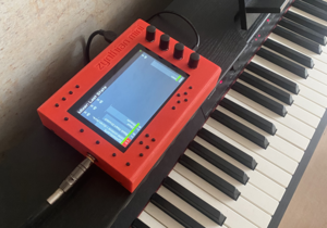
Zynthian Mini kit is a cost effective approach to build zynthian with intention to give opportunity:
- to zynthian developers to get functional zynthian similar to v5 where they can do most of the testing
- to musician to get to know zynthian and learn their features before deciding to but the professional kit
To save the cost of the build Zynthian MINI is lucking capabilities that some of professional musicians really need on stage such as audio-in, TRS audio connectors, best in class DAC for audio out or a rigid metal case.
The main features of zynthian MINI are:
- include encoders and switches that controll zynthian software in the same way as official zynthian v5 kit using the MCP23017 i/o extender
- include MIDI IN, MIDI OUT and MIDI THRU
- include a I2S DAC for AUDIO OUT based on PMC5102 chip that is affordable to buy
- does not need any cabling inside for easy assembling
- does not need the case to test it but it include design of two type of enclosure
- simple enclosure that only cover the top and bottom part of the device that can be also produced in the same way as PCBs
- full enclosure that can be 3d printed
- all connectors are easy to reach (V1 does not have RPI connectors aligned to the edge of the PCB)
Zynthian is currently at version 2. Previous version 1 was more similar to official V4 kit with only 4 buttons but it is not maintained anymore.
To assemble zynthian mini V2 version you will require:
- PCB that need to be produced based on KiCad design that you can find in zynthian hardware repository.
- Components that need to be soldered to this PCB.
- 5" Screen
- Raspberry Pi 4 with heatsink
- optional: zynthian MINI V2 3d printable case
1 Assembling the PCB
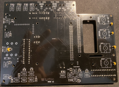
NOTE: Do not be confused that some of the instruction images shown here do not fully align to V2 PCB layout. This is because they are taken with original MINI V2 PCB that had few issues that are now fixed and therefore some small change will be there. Always read the label of the component on the PCB if confused.
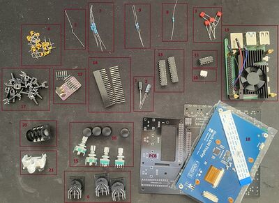
1.1 Components required
1. Capacitors - Electrolytic - Polarized
- Value: 470u 10V
- PCB label: C1
- Package: CP_Radial_D8.0mm_P3.50mm
- Quantity: 1
- Where to buy: https://www.aliexpress.com/item/1005003189675117.html
2. Capacitor - Electrolytic - Polarized
- Value: 100u
- PCB label: C4
- Package: CP_Radial_D6.3mm_P2.50mm
- Quantity: 1
- Where to buy: https://www.aliexpress.com/item/1005003189675117.html
3. Capacitor - Film - Non-Polarized
- Value: 100n
- PCB label: C2,C3,C5,C6,C7
- Package: C_Rect_L7.0mm_W2.0mm_P5.00mm
- Quantity: 5
- Where to buy: https://www.aliexpress.com/item/1005005894912292.html
4. Capacitors - Ceramic - Non-Polarized 100n and 10n
- Value: 100n
- PCB label: C22,C16,C19,C13,C23,C20,C9,C26,C27,C32,C8,C18,C21,C34,C33,C17,C25,C11,C24,C31,C12,C15,C10,C14
- Package: C_Rect_L4.0mm_W2.5mm_P2.50mm
- Quantity: 24
- Where to buy: https://www.aliexpress.com/item/1005002290441861.htm
- Value: 10n
- PCB label: C30,C29,C35,C37,C38,C28,C39,C36
- Package: C_Rect_L4.0mm_W2.5mm_P2.50mm
- Quantity: 8
- Where to buy: https://www.aliexpress.com/item/1005002290441861.htm
5. Diode
- Value: 1N4148
- PCB label: D1
- Package: D_DO-35_SOD27_P7.62mm_Horizontal
- Quantity: 1
- Where to buy: https://www.aliexpress.com/item/32660088529.html
6. MIDI Connectors - PCB mountable
- PCB label: MIDI-OUT-J1, MIDI-IN-J1, MIDI-THRU-J1
- Package: MultiDIN5
- Quantity: 3
- Where to buy: https://www.aliexpress.com/item/1005005773478404.html
7. Resistors
- Value: 220R
- PCB label: R1,R3,R5,R4,R6
- Package: R_Axial_DIN0207_L6.3mm_D2.5mm_P7.62mm_Horizontal
- Quantity: 5
- Where to buy: https://www.aliexpress.com/item/1005005669886834.html
8. Resistor
- Value: 1k
- PCB label: R2
- Package: R_Axial_DIN0207_L6.3mm_D2.5mm_P7.62mm_Horizontal
- Quantity: 1
- Where to buy: https://www.aliexpress.com/item/1005005669886834.html
9. Resistor
- Value: 10k
- PCB label: R8,R7
- Package: R_Axial_DIN0207_L6.3mm_D2.5mm_P7.62mm_Horizontal
- Quantity: 2
- Where to buy: https://www.aliexpress.com/item/1005005669886834.html
10. Digital Optocoupler
- Value: H11L1M
- PCB label: U2
- Package: DIP-6_W7.62mm
- Quantity: 1
- Where to buy: https://www.aliexpress.com/item/32867427644.html
11. Hex inverting Schmitt trigger
- Value: 74HCT14
- PCB label: U1
- Package: DIP-14_W7.62mm
- Quantity: 1
- Where to buy: https://www.aliexpress.com/item/33020259485.html
12. Sound Card PCM5102
- Value: GY-PCM5102
- PCB label: A1
- Package: GY-PCM5102
- Quantity: 1
- Where to buy: https://www.aliexpress.com/item/1005002898278583.html
13. I/O Expander
- Value: MCP23017_SP
- PCB label: MCPMCP23017_SP1, MCPMCP23017_SP2
- Package: DIP-28_W7.62mm
- Quantity: 2
- Where to buy: https://www.aliexpress.com/item/1005005363863079.html
14. 2x20 Pin Header - male and female
- Male:
- PCB label: HAT1
- Package: PinSocket_2x20_P2.54mm_Vertical
- Quantity: 1
- Where to buy: https://www.aliexpress.com/item/4000133266617.html
- Female:
- PCB label: RPi1
- Package: two spacer female 40pin vertical header
- Quantity: 1
- Where to buy: https://www.aliexpress.com/item/4001095693537.html
15. Encoder with a Switch
- Value:
- PCB label: Enc2,Enc4,Enc1,Enc3
- Package: RotaryEncoder_Alps_EC12E-Switch_Vertical_H20mm
- Quantity: 4
- Where to buy: https://www.aliexpress.com/item/1005006142236380.html
16. Encoder Cap
- Value: encoder caps
- PCB label: Encoder caps
- Package: Encoder caps
- Quantity: 4
- Where to buy: https://www.aliexpress.com/item/1005005835327286.html
17. Push Button
- Value:
- PCB label:SW14,SW9,SW16,SW20,SW6,SW10,SW8,SW2,SW17,SW4,SW12,SW19,SW5,SW1,SW13,SW18,SW15,SW7,SW11,SW3
- Package: push-button
- Quantity: 20
- Where to buy: https://www.aliexpress.com/item/32912263133.html
18. 5" DSI Screen for Raspberry Pi
- Value: Screen
- PCB label: RPI 5" screen
- Package: RPI screen
- Quantity: 1
- Where to buy: https://www.aliexpress.com/item/1005005353135304.html
19. Raspberry Pi 4 4GB with heatsink
- Where to buy heatsink: https://www.aliexpress.com/item/1005004774833369.html
20. 1/4 Stereo jack
- Value: J1
- PCB label: J1
- Package: Jack_6.35mm_Neutrik_NMJ6HFD2_Horizontal
- Quantity: 1
- Where to buy: https://www.aliexpress.com/item/4001266094691.html
21. RCA Stereo jack
- Value: J2
- PCB label: J2
- Package: RCA RS-234
- Quantity: 1
- Where to buy: https://www.aliexpress.com/item/1005001629197904.html
1.2 Soldering
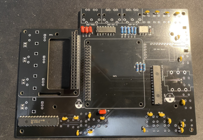
First get PCB and all components sorted by their type. Check their values using digital multimeter to make sure that you have them properly sorted.
Heat up the solder iron and make sure that its tip is clean. If not put some solder on it and clean it with wet sponge. It has to be shiny silver tip.
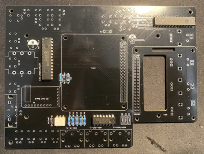
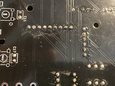
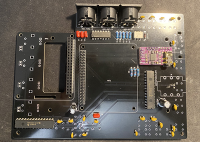
Start by soldering back side of the PCB. Order of soldering is always from smallest to tallest components.
First solder resistors and diode and microchips such as Digital optocoupler (H11L1M), hex inverting schmitt trigger (74HCT14) and I/O Expander (MCP23017). Pay attention to orientation of these microchips.
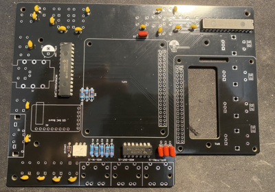
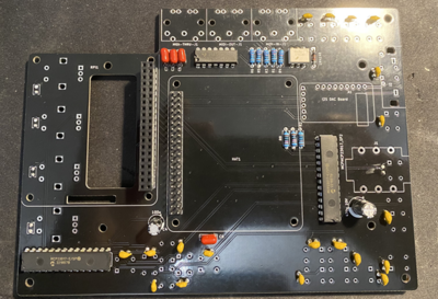
Solder the ceramic and film capacitors at the back of PCB (orientation not important - they are non polarized).
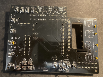
Then solder film and ceramic capacitors at the front (orientation not important - they are non polarized).
Then solder female and male headers
Then solder two electrolytic capacitors. Pay attention to their orientation.
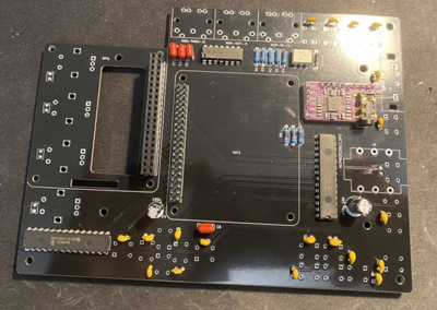
Then solder sound card. First solder male header pins that came with the card and the solder it to PCB board.
Make sure that you have cut sound card pins - they are too long and they will touch the screen if you leave them as it is.
Then solder three MIDI connectors.
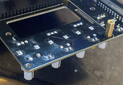
Then solder the switches.
Finally solder the encoders. After soldering them cut any excess wires because that side will be very close to RPI heatsink so any contact to it must be avoided.
You have finished the hard part - soldering. Now you just need to assemble everything together.
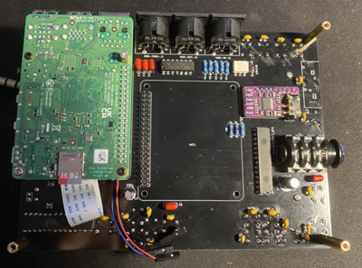
1.3 Assembling the PCB for the test
This instruction here are just assembling everything for testing. You should test it before assembling into the case.
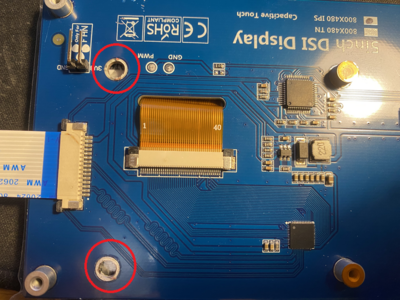
First remove two screen posts that are not necessary and could touch some of the PCB components.
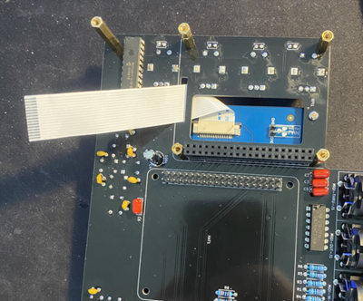
Then connect longer cable that comes with a screen to the screen and attach the screen to PCB.
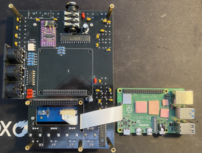
Then screw appropriate hex mounts to PCB for Raspberry Pi. Do not connect Raspberry Pi yet. The type of hex mounts will depend on heatsink that you use. Also connect the screen cable to RPI.
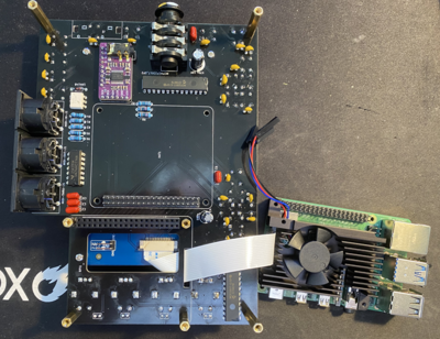
Then connect heatsink to raspberry pi.
Then connect raspberry Pi to PCB.
1.4 Configure Zynthian MINI V2 for testing
Once everything is configured and working it is a time to put zynthian into the enclosure.
