Build a Zynthian
Jump to navigation
Jump to search
1 How to build a Zynthian (Prototype-3)
Manual is currently in development! (20150406)
1.1 Prerequireries
Want to join the Zynthian community? No problem! Build your own one is not very difficult.
1.1.1 Needed competences
For building the hardware you should have the following competences:
- Soldering
- Not to be afraid working with electronic hardware and parts
- Basic understandment of reading electronic circuit diagrams
1.1.2 Tools
- Screw drivers
- Soldering iron
- Tin-solder
- Side cutter
1.2 Hardware
1.2.1 Bill of Material
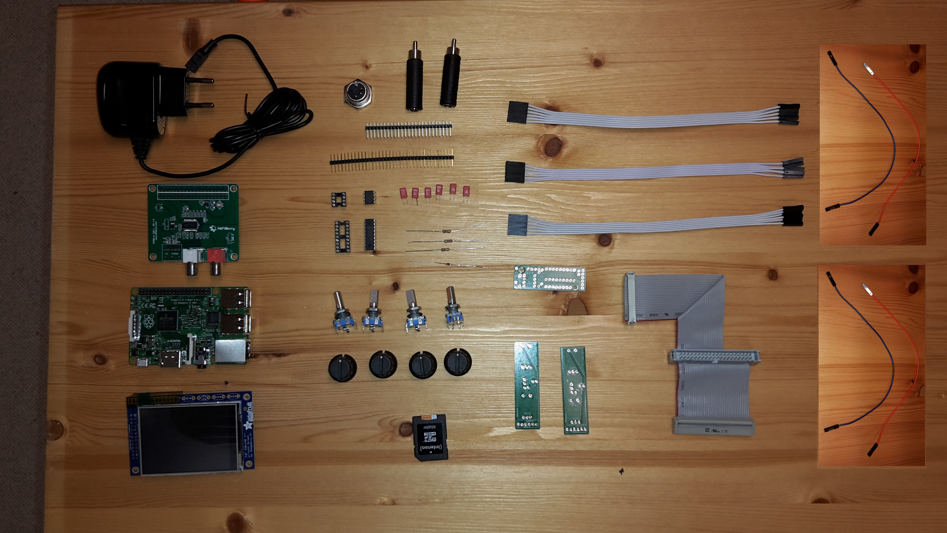
Here is a list of hardware you need. I have noticed also where I bought the hardware and the price. This items are bought in February 2016 in Germany, so all descriptions are in german and prices are in EUR. If you live in other countries there maybe are better sources of supply for you in your home country.
| No | Shipper | Order no. | Description | Pieces | Price per piece [€] |
|---|---|---|---|---|---|
| 1 | http://www.reichelt.de | 1N 4148 | Planar Epitaxial Schaltdiode, DO35, 100V, 0,15A | 1 | 0,04 |
| 2 | http://www.reichelt.de | 6N 138 | OPTOKOPPLER | 1 | 0,58 |
| 3 | http://www.reichelt.de | RASPBERRY PI 2 | Raspberry Pi 2, 4x 900 MHz, 1 GB RAM | 1 | 37,50 |
| 4 | http://www.reichelt.de | RPI HB DAC+ RCA | HiFiBerry DAC+ RCA, Raspberry Pi Shield | 1 | 35,90 |
| 5 | http://www.reichelt.de | 1/4W 220 | Kohleschichtwiderstand 1/4W, 5%, 220 Ohm | 1 | 0,10 |
| 6 | http://www.reichelt.de | 1/4W 1,0K | Kohleschichtwiderstand 1/4W, 5%, 1,0 K-Ohm | 1 | 0,10 |
| 7 | http://www.reichelt.de | 1/4W 10K | Kohleschichtwiderstand 1/4W, 5%, 10 K-Ohm | 1 | 0,10 |
| 8 | http://www.reichelt.de | MKS-02 100N | WIMA Folienkondensator, Rm 2,5mm 100nF | 4 | 0,15 |
| 9 | http://www.reichelt.de | GS 18P | IC-Sockel, 18-polig, superflach, gedreht, vergold. | 1 | 0,32 |
| 10 | http://www.reichelt.de | GS 8P | IC-Sockel, 8-polig, superflach, gedreht, vergold. | 1 | 0,19 |
| 11 | http://www.reichelt.de | SL 2X25G 2,54 | 2x25pol.-Stiftleiste, gerade, RM 2,54 | 1 | 0,24 |
| 12 | http://www.reichelt.de | MAB 5S | DIN-Buchse, 5-polig | 1 | 0,24 |
| 13 (OPTIONAL) | http://www.reichelt.de | NTA 176 | 6,3 Mono-Klinken-Bu. auf Cinch-St. | 2 | 0,35 |
| 14 | http://www.reichelt.de | NT MUSB 2 SW | Micro-USB Steckernetzteil, schwarz, 5 V, 2 A | 1 | 8,40 |
| 15 | http://www.segor.de | MCP23008-E/P | MCP23008 8 port I2C-GPIO extender | 1 | 2,10 |
| 16 | http://www.amazon.de | Adafruit PiTFT 2.8" | Adafruit PiTFT Touchscreen Display, 2,8 Zoll, für Raspberry Pi Computer | 1 | 32,00 |
| 17 | http://www.ebay.de | 12mm Rotary Encoder Switch | Rotary Encoder with switch, 20 steps | 4 | 0,60 |
| 18 | http://www.ebay.de | Poti knob | Poti knob for Rotary encoder (Pos. 17) | 4 | 1,50 |
| 19 | http://blog.zynthian.org | Encoder PCB | PCB for encoders | 2 | 10,00 |
| 20 | http://blog.zynthian.org | 2in1 PCB | PCB for MIDI and GPIO extension | 1 | 10,00 |
| 21 | http://blog.zynthian.org | Main Bus Ribbon Cable | Raspberry Main Bus Ribbon Cable | 1 | 20,00 |
| 22 | http://blog.zynthian.org | Mini-ribbon cable | Mini-ribbon cable (6 pin female connector to 6 female jumper connectors | 3 | 3,00 |
| 23 | http://www.saturn.de | SD card | Samsung 32GB SD card | 1 | 14,00 |
| 24 | - | Short connector cables | Connector cables for MIDI and external GPIO connector from 2in1 board | 4 | ??,?? |
| 25 | - | Multi-pin connector | 1x40pol.-Stiftleiste, gerade, RM 2,54 | 1 | ??,?? |
Notes:
- Pos. 19-22 are directly ordered from Zynthian.
- There is no case in this BoM - You have to build your own.
- Sum of all is: 200,27 € (plus shipment)
1.3 Implement and soldering of the PCBs
1.3.1 Step 1: 2in1 board
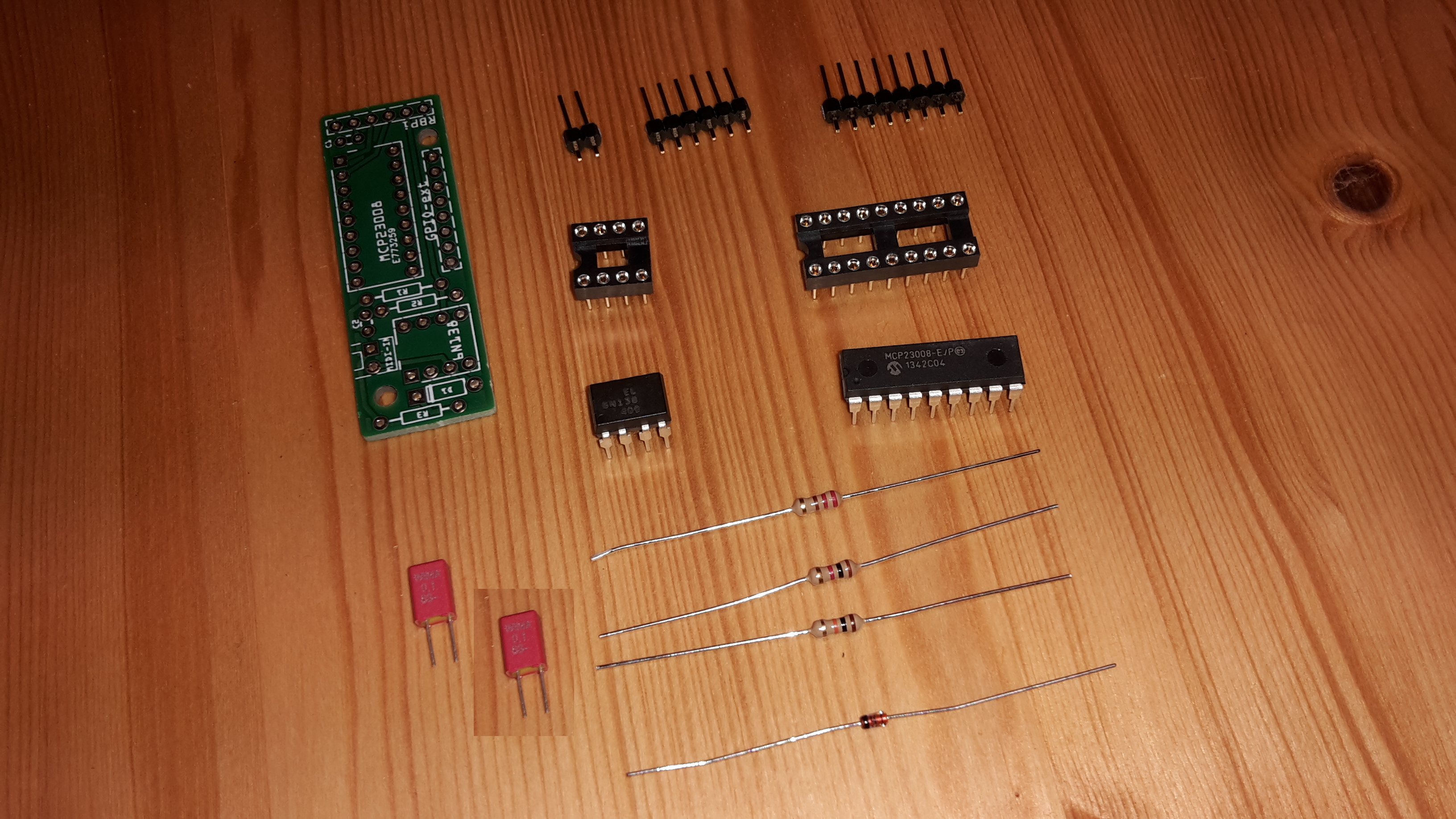
1.3.1.1 You need:
- 1 * 2in1 PCB (Pos. 20)
- 2 * 100nF capacitor (Pos. 8)
- 1 * multi-pin 2 pins wide (part of Pos. 24)
- 1 * multi-pin 6 pins wide (part of Pos. 24)
- 1 * multi-pin 8 pins wide (part of Pos. 24)
- 1 * resistor 10 kOhm (brown-black-orange-gold, Pos. 7)
- 1 * resistor 1 kOhm (brown-black-red-gold, Pos. 6)
- 1 * resistor 220 Ohm (red-red-black-gold, Pos. 5)
- 1 * diode 1N4148 (Pos. 1)
- 1 * IC socket 8 pins (Pos. 10)
- 1 * IC socket 18 pins (Pos. 9)
- 1 * IC 6N138 (Pos. 2)
- 1 * IC MCP23008 (Pos. 15)
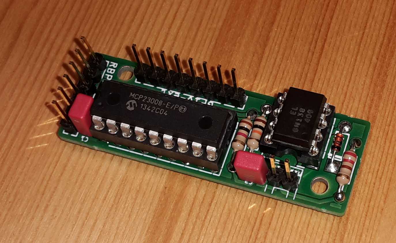
1.3.1.2 HowTo:
- Start with assembling the diode onto the PCB. Be careful to do this the right way - the small black (or white) stripe on one side of the diode must fit the same side of the white stripe on the PCB!
- After that solder the resistors.
- Then assemble the IC sockets, but do not put the ICs inside. We will do this at the end of this task.
- After that, solder the capacitors and the multi-pin-rows.
- Now insert the ICs into the socket. Be careful to put them weith the notch on the IC towards the hole of the white rectangle showing on the PCB!


