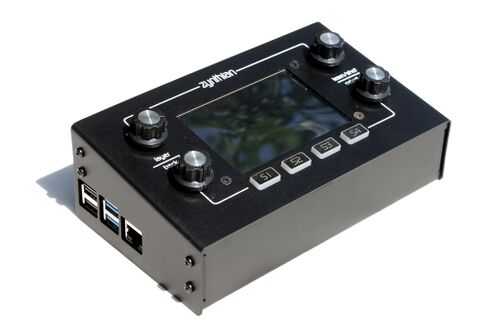
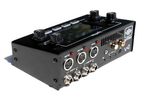
Building a Zynthian Box using an official Kit v4.1
1 Introduction
This tutorial is intended for those building a Zynthian Box using one of the official kits, that i offer here:
Zynthian Shop
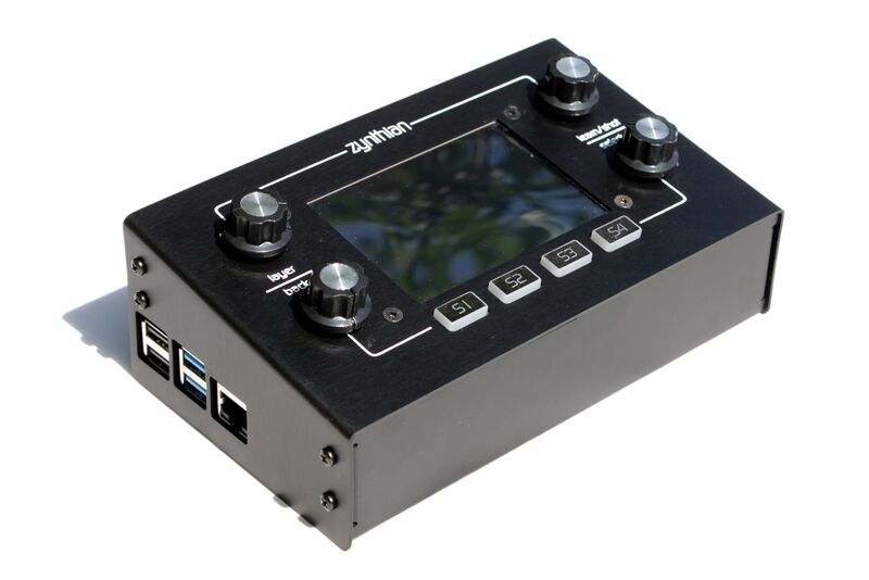
Specifically, these instructions are for assembling the Zynthian Kit v4.1, that includes the Hifiberry DAC+ADC Stage with the Zynaptik circuit and the ZynScreen v1.5 display.
2 List of Materials
- Zynthian Kit v4
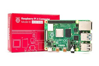
- Raspberry 4 Computing Board
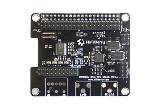
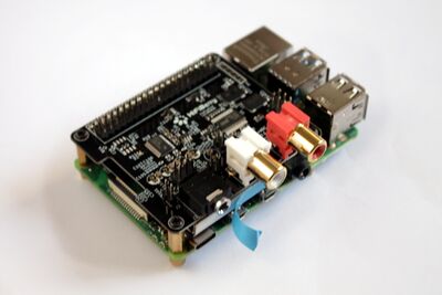
- HifiBerry DAC+ADC STAGE souncard
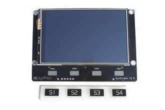
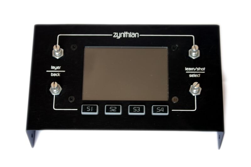
- ZynScreen v1.5 (3.5" touch-display + controllers I/O + rubber silicon button)
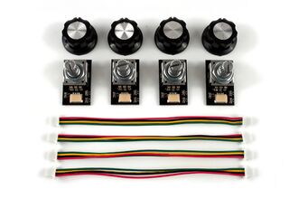
- 4 x controllers v4
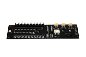
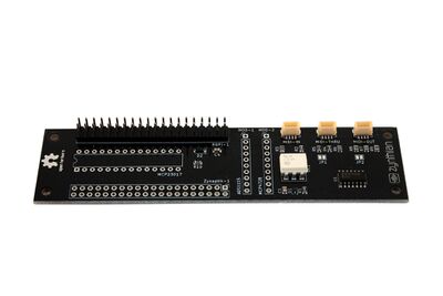
- Zynaptic module (MIDI IN/THRU/OUT & extended I/O)
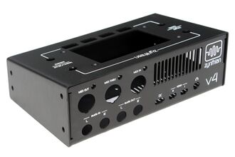
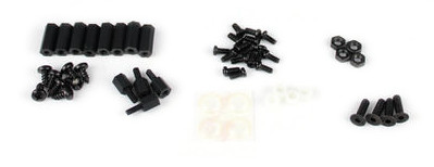
- Aluminum Case v4 (including zynductor passive cooling, bolts & nuts)
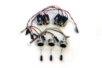
- Pre-built case-connectors (with soldered harnesses)
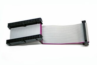
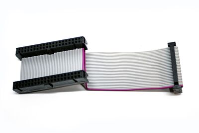
- Ribbon bus cable
- Power supply for RBPi 4 (5.1v 3A with USB type-C connector) => Not included on official kits!
- 16GB micro-SD card or bigger (Use a high-quality card) => Not included on official kits!
3 Some definitions
3.1 Zynthian
It's an open project with the goal of creating an Open Synth Platform based in Free Software and Open Hardware specifications & designs.
3.2 Zynthian Software
The Zynthian Software stack consist of:
+ GNU Linux Operating System: RaspberryPi OS Buster (Debian Buster)
+ Jack Audio Daemon
+ A collection of standalone Synth Engines & LV2 Plugins (see Supported Synth Engines & Plugins)
+ MOD-HOST + MOD-UI software, from ModDevices (github repositories)
+ Zynthian User Interface (github repository)
+ Zynthian Webconf Tool (github repository)
All the software used by Zynthian is Free Software (free as in freedom, not as in free beer), and it's covered by the GPL license or similar. If you don't know what Free Software is, take a look at this link:
What is Free Software?
The easiest way of getting the software is downloading the last official SD image from here:
Download Last Stable ZynthianOS SD-image
It's a compressed image file (plenty of soundfonts) compiled for Raspberry Pi 3. The SD-card images include all the Zynthian software, properly configured for working with the official kits. Completely ready to use. Plug and play!
After downloading the SD-image, you have to write it to your micro-SD card. You need a micro-SD card with a minimum size of 16 GB.
If you don't know how to do it, you can use Etcher (free software, works on Mac, Windows or Linux) to flash the image onto the micro-SD card. Or do it manually! There is a really good manual for this at this link.
you can also build your own SD image following these instructions:
Building the SD Image using the Setup Script
3.3 Zynthian Box
A Zynthian Box is a hardware device: a small computer designed to run the Zynthian Software. It's currently based on the Raspberry Pi platform, but it could easily be adapted to other computer platforms.
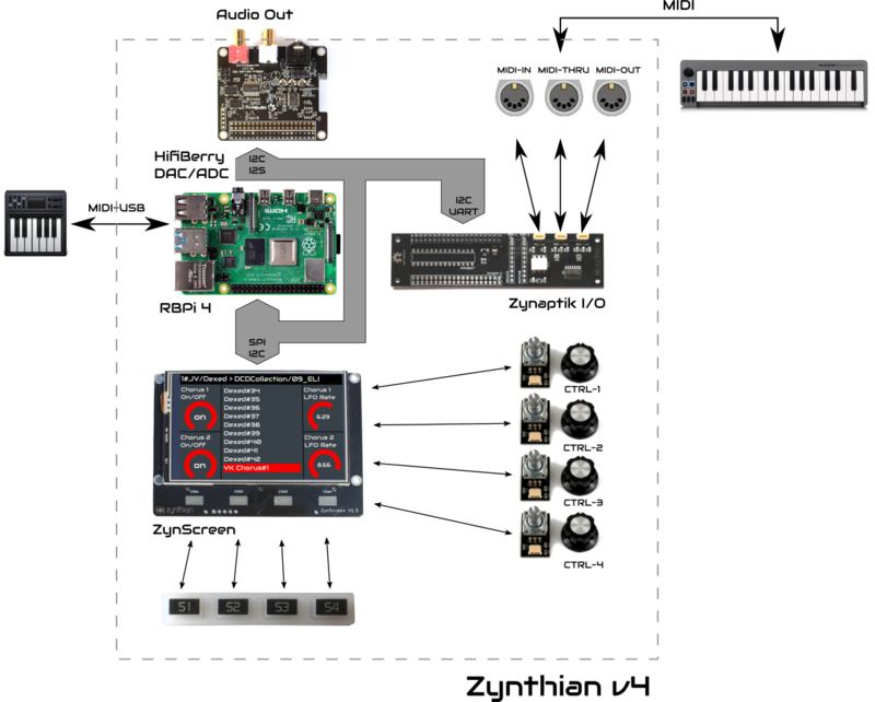
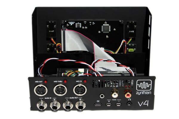
This is a sketch with the components the official Zynthian Box is made of:
In the project's repositories you can find all the electric schemes, PCB specifications, Herber files, etc. to build your own Zynthian Box from scratch:
- Zynthian Hardware Repository
- Zynthian Case Repository
The official version is the canonical reference. Of course, you don't have to build the official version. You can build your customized Zynthian Box modifying and improving what you want. If you do so, feedback would be appreciated.
3.4 Zynthian Kit v4
A Zynthian Kit is a set of electronic and mechanic parts. The official Zynthian Kit v4 consists of these parts:
+ 1 x Raspberry Pi 4
+ 1 x Hifiberry DAC+ADC PRO
+ 1 x ZynScreen v1.5: Touch-Display 3.5" + Controllers circuit + Silicone buttons
+ 4 x Controller Modules + Wiring
+ 1 x Zynaptik Module: MIDI Ports + extended I/O
+ 1 x Ribbon bus cable
+ 1 x Zynthian Aluminium Case
+ 1 x Connectors Set
+ 1 x Bolts & Nuts Set
+ 1 x Zynductor
3.5 Unboxing the Zynthian Kit v4
4 Assembling your Zynthian Box
4.1 Prerequisites
Assembling your Zynthian Kit V4 is not difficult at all: you need all your attention, a screwdriver, an adjustable wrench, a cutter and adhesive tape. You don't need to solder anything, just put it together and connect the wires.
Read the instructions and observe the detailed photos carefully. Both!! If you get in trouble you can ask the community:
https://discourse.zynthian.org
WARNING!!
Please, handle electronic parts with care, specially the display, as they are easily damaged.
Let's go!!
4.2 Secure the balanced audio output jack-TS connectors
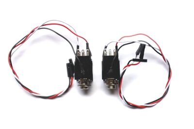
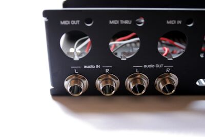
These 2 connectors are pre-assembled together and share a single harness with 3 wires ended with a 3-pin dupont connector.
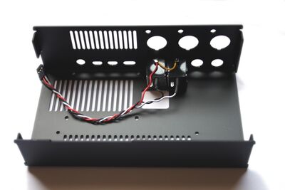
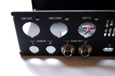
Insert the jack connectors into the 2 holes labeled as audio OUT. You have to insert them from inside the case and secure them with the washers and nuts from the outside. The washers will keep the nut from damaging the case. Use a wrench for tightening the nuts, but not too much!!
4.3 Secure the balanced audio input jack-TRS connectors
These are 2 separated connectors with a 3-wire harness each, ended with 3 x 1-pin dupont connectors.
Insert the jack connectors into the 2 holes labeled as audio IN. You have to insert them from inside the box and secure them with the washers and nuts from the outside. The washers will keep the nut from damaging the case. Use a wrench for tightening the nuts, but not too much!
4.4 Secure the MIDI connectors
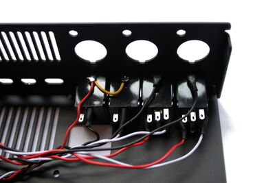
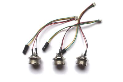
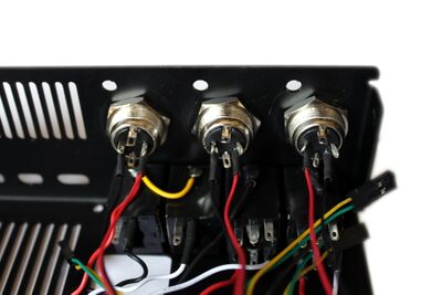
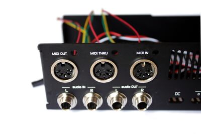
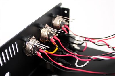
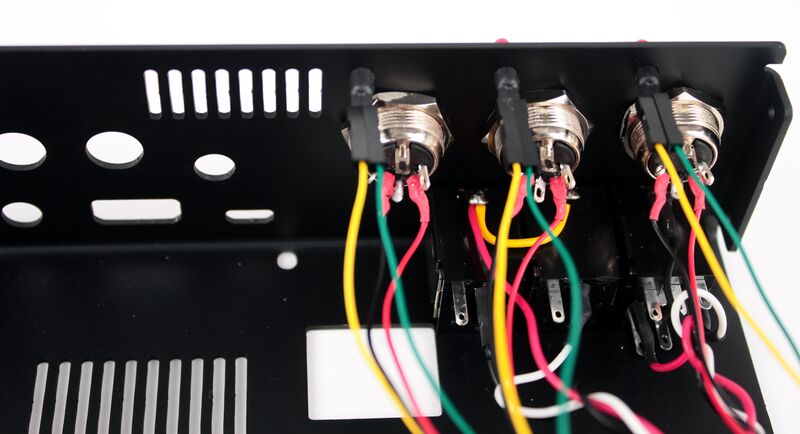
There are 3 standard MIDI connectors (DIN-5) mounted with their harnesses.
Insert each MIDI connector in the 3 holes labeled as MIDI OUT/THRU/IN. You have to insert them from the outside and secure them with the nut from the inside. Start from the MIDI-OUT and end with the MIDI-IN, using a wrench to tighten the nuts.
4.5 Mount the MIDI activity LEDS
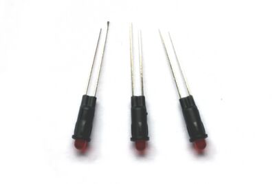
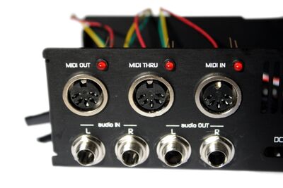
Insert the 3 LEDS in the case from the outside, leaving the short lead at left. Make sure you push the LEDs by the plastic around the LED, not the LED itself.
When it's done, you have to plug the LED wires into the 2 spare "DUPONT" connectors from the MIDI harness (green & yellow wires). Polarity is important, so don't cross the wires:
* JST Green wire (1) => LED's Anode (LED's long lead)
* JST Yellow wire (2) => LED's Cathode (LED's short lead)
Since the LED's leads are too long, you will want to cut them down to about 7-8mm. Make sure you remember which lead is the short one. When inserting the dupont connector, if you feel that it doesn't grab the pins enough, you should press the tiny metal-jacket inside the plastic capsule to make it narrow. It's easy, simply put the dupont connector over the desk and press the metal with the screwdriver tip or something like that.
Note:
If you don’t connect the status LEDs, the MIDI-OUT and MIDI-THRU won’t work unless you short the JP1 & JP2 jumpers on the zynaptik board.
4.6 Prepare the Zynductor Passive Cooler
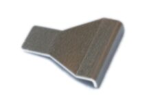
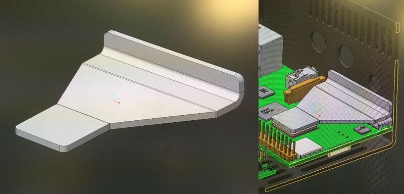
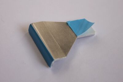
The Zynductor passive cooler is a little piece of aluminum that sticks to the RBPi's CPU and the aluminum case, creating a thermal channel for evacuating the heat generated by the RBPi's CPU.
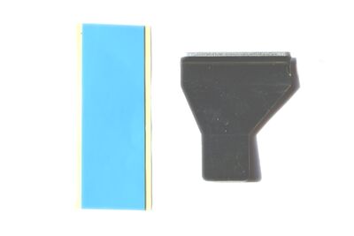
For fixating the Zynductor we will use double-side thermal tape:
1. Cut the thermal tape in 2 pieces. One of 4cm long and the second one of 2cm long.
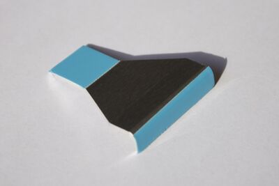
2. Remove the protective yellow paper from the long piece and stick the tape carefully on the zynductor, taking care of covering the long area that contacts the aluminum case. Use a cutter to remove the excess.
3. Repeat the procedure with the short piece and the square area that contacts tha RBPi's CPU.
4.7 Secure the Main Computing Block and assemble the Zynductor Passive Cooler
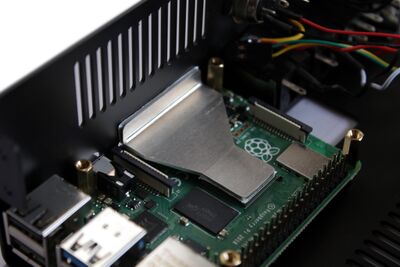
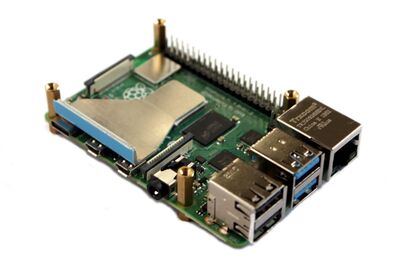
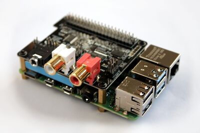
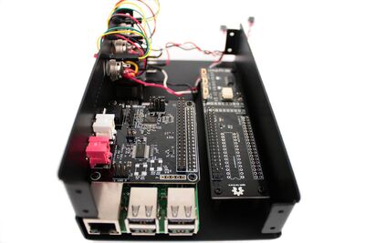
The main computing block consists of the Raspberry Pi and the HifiBerry soundcard,and is assembled using separators and bolts. The Zynductor passive cooler is a little piece of aluminum that sticks to the RBPi's CPU and the aluminum case, creating a thermal channel for evacuating the heat generated by the RBPi's CPU. For getting the best performance, you have to put all your attention and follow carefully these steps:
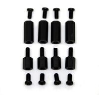
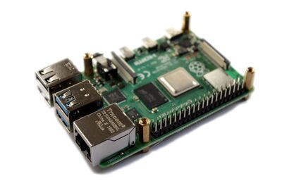
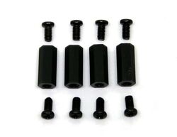
1. Fix the 2x4 separators to the Raspberry Pi. Put the longest of the two on top of the Pi and the shorter at the bottom.
2. Secure the Raspberry Pi to the bottom of the aluminum case using 4 tiny black bolts M2.5
 3. Remove the blue protective cover from the zynductor's square contact area, the one that contacts the RBPI's CPU. Don't remove the other one yet!!
 4. Stick the zynductor over the RBPi's CPU, taking special care of assuring the contact between the aluminum case and the zynductor's long contact area, the one with the blue protective cover still there.
 5. Remove the RBPi from the case, untightening the tiny black blots.
 6. Plug-in the HifiBerry soundcard on to the Raspberry Pi.
 7. Fix the 4 screws on top of the HifiBerry to fix it in place.
 8. Remove the blue protective cover from the zynductor's long contact area, the one that contacts the aluminum case.
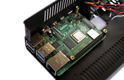
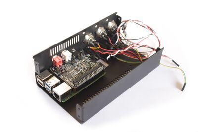
 9. Finally, fix the main computing block to the case, using the 4 remaining tiny black bolts M2.5 to secure it to the bottom of the case.
4.8 Secure the Zynaptik module
Secure the Zynaptik module to the case using 4 x separators and 8 x M2.5 screws. Begin by mounting the separators to the bottom of the case, and attach the module to the separators using the remaining screws.
The zynaptik board has some extra circuitry which doesn't have anything soldered on it. These are used for adding extra functionality to the board.
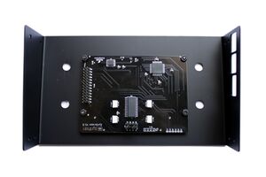
4.9 Mount the Display
WARNING!!
Please, handle electronic parts with care, specially the display, as it is easily damaged.
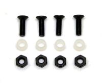
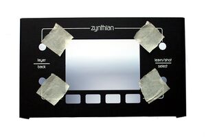
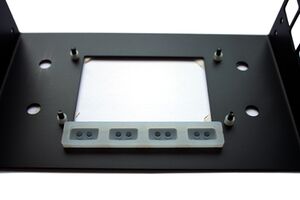
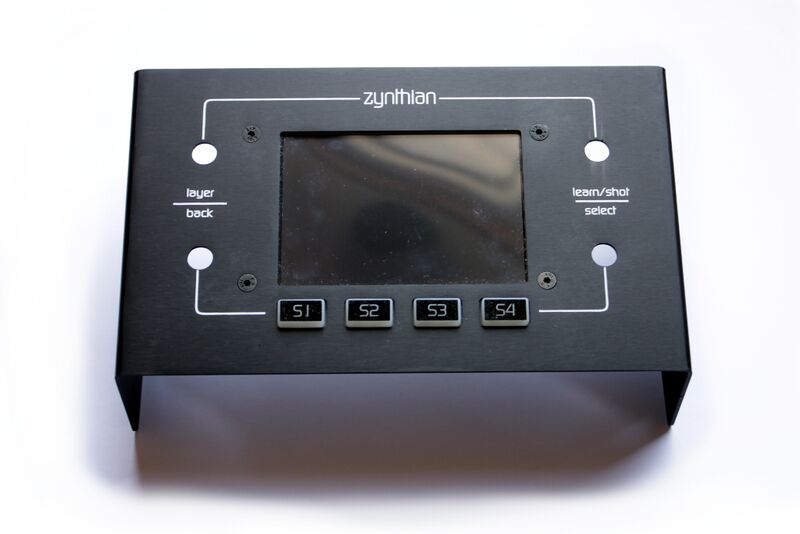
The screen is secured with these 4 screws, nuts, and nylon separators. Mount the screen by screwing the screws from the outside and fixing them with the bolts from the inside. The separators go between the screen and the case, same that the silicone keypad. Remember to remove the protective film from the screen before mounting it.
4.10 Mount the Controllers
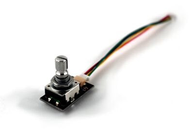
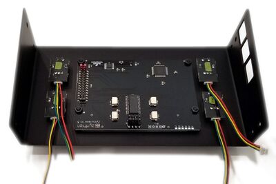
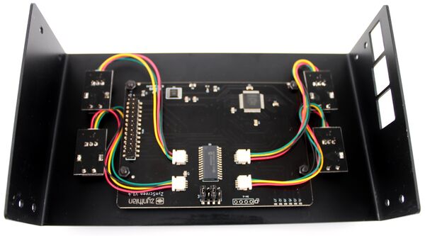
Plug a wire on each controller. Fix the controllers in each corner using the nuts and washers attached to them.
Don't mount the controllers like in the photo, do it upside-down to avoid pressing the MIDI LED pins. I will update the photo ASAP.
4.11 Attach the knobs
You should attach the knobs into the encoders before closing the case. Push the knobs unto the encoders while pushing the encoder with a finger on the PCB board. This will avoid putting too much pressure on the encoders, which can break them. The knobs can be very tight, and a bit of water can be used as lubricant to help with this.
4.12 Attach the rubber feet
5 Connecting everything
The Zynthian Kit 4 is designed to use JST connectors which can't be plugged in wrong, so connecting everything is straight-forward:
5.1 Connect the Ribbon Bus cable
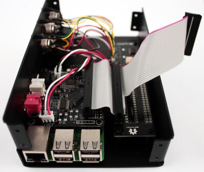
Connect the Main Ribbon Bus cable to the Raspberry Pi's 40-pin header and to the Zynaptik module. The red wire is pin 1, so if you are looking at the case from the front, it should be on the right.
5.2 Connect the Controllers
Connect the 4 controller cables to the 4 controller connectors on the ZynScreen (CTRL1, CTRL2, CTRL3, CTRL4). Wire color order doesn't matter. Harness wires are crossed, so depending what connector did you plug on the encoder side, you have to plug the other one on the display. There are 2 combinations.
5.3 Connect the MIDI connectors & activity LEDs
Connect the 3 cables from the MIDI connectors to the MIDI-IN, MIDI-OUT and MIDI-THRU connectors on the Zynaptik module.
Note:
If you don’t connect the status LEDs, the MIDI-OUT and MIDI-THRU won’t work unless you short the JP1 & JP2 jumpers on the zynaptik board.
5.4 Connect the Audio Output Jack connectors
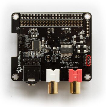
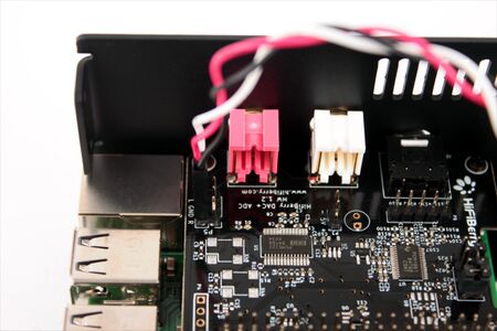
Connect the audio output jack connectors to the audio-output header to the Hifiberry soundcard:
The black wire on the "R" pin, white on the "L" one and red on "GND" (middle).
Note:
Some kits have flipped the red and white wires. This is not a problem. Simply look at the black wire.
5.5 Connect the Audio Input Jack connector
This step depends of the specific model of your soundcard:
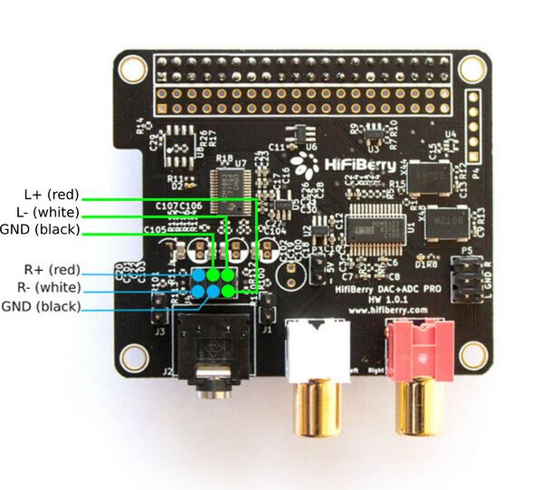
5.5.1 HifiBerry DAC+ADC PRO
Connect the 2 x balanced input jack connectors to the audio-input header on the sound card using the 3x1 pin Dupont connectors as indicated in the image:
I recommend you take a look at Hifiberry DAC+ADC PRO specification.
5.6 Connect the Display
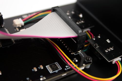
Connect the ribbon's 26-pin connector to the display's connector. Pay attention to the orientation. The red wire should be the pin 1, which as marked on the display's PCB surface. Probably you need to remove the red-jumper that is plugged in the connectors pins 1-2, indicating the right position.
WARNING!!
Please, double check this step carefully because you could break the display if it's connected reversed!!
And that's all!! Your Zynthian Box is almost ready to boot. I recommend that you double-check everything before powering up the device.
6 Testing your Zynthian Box
6.1 Double-check the parts and wiring
It's easy to make a mistake while assembling the parts or connecting the wires. Some errors can be dangerous for the electronic components (such as short circuits) so it's better to be sure that everything is correctly assembled and connected.
Pay attention to ribbon bus connection and verify that red wire is on pin 1 for every connector. Pay attention to the audio jack connectors and make sure they are connected correctly to the Hifiberry sound card.
6.2 First Boot
When you are sure that everything is in its place, it's time to boot the machine:
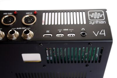
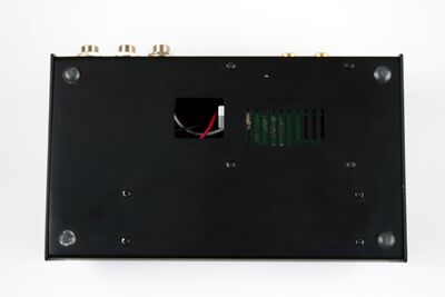
1. Insert the SD-card with the zynthian image. If you don't have one yet, read this. You can insert the SD-card through the "window" on the bottom-side of the case.
2. Plug the mini-usb power connector. A good 5V micro-usb charger is recommended (> 2 Amp).
These are the stages that you should see while booting:
1. After 5-10 seconds, it will show the Zynthian splash screen
2. After 3-4 seconds, it will go black
3. If you are using a fresh zynthian image and it's the first boot, the stages 1 and 2 will be repeated
4. After 5-10 seconds, the zynthian UI will be shown
If you get the Zynthian UI, then you have assembled the Zynthian box correctly. Congratulations!
If you don't get an error screen or a blank screen, you probably you made a mistake during the assembly. You have to locate and solve the problem(s).
If you are using the Aruk RC-3 SD image (which you should), you will notice that the controllers are not working at all. This SD image is pre-configured for working with the kit v2, so you need to configure the software for working with the kit v3. The simplest way of doing it is using the webconf tool:
- Connect your zynthian to your local network using an ethernet cable (RJ-45).
- From your web browser, access the zynthian's webconf tool by typing "zynthian.local" in the address bar. If this doesn't work for you, you should try with the IP. You can get the IP of your zynthian by navigating to the Admin Menu and clicking "Network Info". You should do that by using the touch interface: Click the top bar with a stick (or your nail, if it's not too wide) until you are in the Admin Menu. Once you are there, go down and click "Network Info".
- Type the password (raspberry) and log into the webconf tool.
- Once you are logged in, you have to access Hardware->Kit and select "Kit V3".
- Save the changes and reboot your Zynthian.
6.3 Test the Controllers & UI
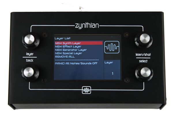
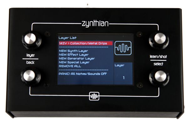
If you get into the Zynthian UI, then you should be in the 'Layer list' screen. Let's start testing that your controllers are working OK.
1. Rotate the SELECT controller up & down for selecting the different options in the Layers menu.
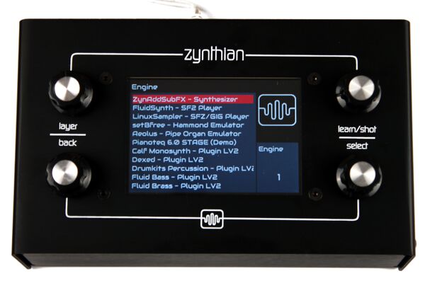
2. Push SELECT to create a New 'Synth Layer'. You should get into the 'Engine Selection' screen.
If it doesn't work, try rotating/pushing the 'learn/snapshot' controller. Perhaps you have cross-wired the 3 & 4 controllers and in that case, you have to fix the wiring. If it doesn't work, try pushing the other two controllers and rotating the controllers. If something happens, most probably you have reversed the wiring when connecting the controllers. Double-check the wiring again.
3. Rotate the SELECT controller to choose the engine you want to instance for the new layer.
The selector must go down when rotating clockwise and go up when rotating counter-clockwise. If the rotation sense is reversed, you should check the wiring. Perhaps one of the connections are faulty. The wires' color sequence should be red, black, yellow, green.
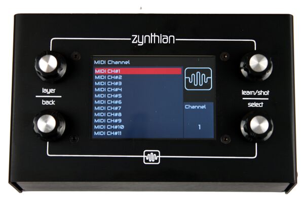
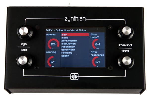
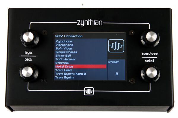
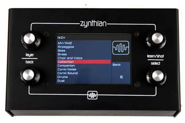
4. Select the ZynAddSubFX engine, select channel #1, select bank 'Collection' and preset 'Metal Drips'.
You should get to the 'Instrument Control' screen.
5. Rotate every control to test that it works and that the rotation sense is correct.
If one of the controllers doesn't work correctly, check the wiring again.
6. Push SELECT to move to the next controller screen. Bold push (a push lasting about 1 second) to select a controller screen from the list.
7. Push BACK. You should go back to the 'Preset Selection' screen.
8. Push BACK again. You should go back to the 'Bank Selection' screen.
9. Push LAYER again to return to the 'Layer Selection' screen. Try to create another layer following the same procedure.
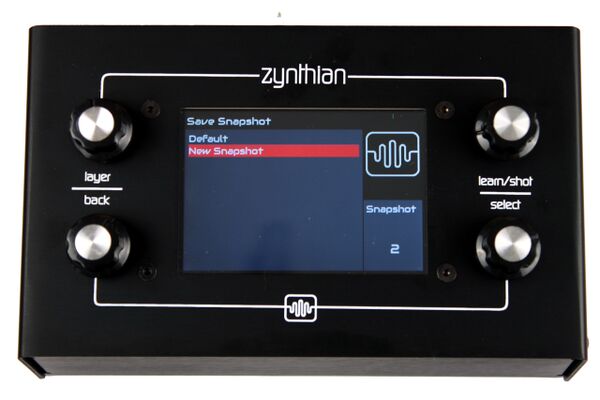
10. Push 'SNAPSHOT' to get into the 'Snapshot' screen. Select 'New Snapshot' and your first snapshot will be stored.
If everything is working OK, then you should read the User's Guide and start enjoying your Zynthian Box, but before that ... why not enjoy it a little bit? Connect your MIDI keyboard, your speakers and check this out:
Bank 'net-wisdom', Preset 'Vangelis Saw - C'
Keep pushing a single note (or a chord) and move the cutoff and resonance controllers. Play around a bit and have some fun
6.4 Test the Audio Output
1. Connect the audio output (RCA or Jack connectors) to your amplifier or auto-amplified speakers.
2. Boot your Zynthian. You should be in the initial 'Layer Selection' screen.
3. Push BACK and you will get into the 'Admin' screen.
4. Select 'Audio Test' option and push 'SELECT'. You should hear the test audio-track: a nice afrocuban track
5. Push 'BACK' to stop the playing, and 'BACK' again to return to the "Layer Selection' screen.
If you hear nothing, check the amplifier, speakers, cabling, gain, volume, etc. If nothing works, you have to locate and solve the problem(s).
6.5 Test the MIDI subsystem
1. Connect the audio output (RCA or Jack connector) to your amplifier or auto-amplified speakers.
2. Boot your Zynthian, select FluidSynth engine, channel #1 and 'TimGM6mb' bank. Select an instrument, like "Piano 1".
3. You could add more layers to complete the band
3. Push BACK, holding the switch down for more than 2 seconds. You should get to the 'Admin' screen.
4. Select 'MIDI Test' option and push 'SELECT'. You should hear the test midi-track ('Take Five') interpreted by your Zynthian's band
5. Push 'BACK' to stop the playing
If you hear nothing, please, check the amplifier, speakers, cabling, gain, volume, etc. If nothing works, you have to locate and solve the problem(s).
6.6 Test the MIDI-USB inputs
1. Connect the audio output (RCA or Jack connector) to your amplifier or auto-amplified speakers.
2. Boot your Zynthian, select ZynAddSubFX, channel #1, bank and an instrument
3. Connect a MIDI-USB keyboard to any USB port. The keyboard should be configured to use channel #1.
3. After 2-3 seconds , play something with your keyboard. A simple Chopin's Nocturni should be enough. You should hear your music. If you don't like it, you should probably take some piano lessons, like me.
If this doesn't work, you have to locate and solve the problem(s).
6.7 Test the MIDI-IN connector
1. Connect the audio output (RCA or Jack connector) to your amplifier or auto-amplified speakers.
2. Boot your Zynthian, select ZynAddSubFX, channel #1, bank and instrument.
3. Connect your keyboard's MIDI-OUT to the Zynthian's MIDI-IN using a MIDI cable.
3. After 2-3 seconds, play something with your keyboard. A single melody can do the trick.
If this doesn't work, you have to locate and solve the problem(s).
7 Final steps
Once everything is in its place and you have tested that it works, it's time to close the case
7.1 Close the case
Take your time to bend and push the cables to get a good fit when closing the case. The ribbon bus cable is pre-bent to make this process easier.
Finally, fasten the 8 sheet-threaded bolts to secure the case, 4 on each side.
8 Update your Zynthian Box
If you are using the official Zynthian SD Image, the first thing you should do after booting up your Zynthian Box and making the controllers are working, is update the software:
- connect your Zynthian Box to your router using an ethernet cable
- from the admin menu, click update software
- from the admin menu, click restart UI (or reboot)
The update process can take some time. Be patient. If you get an error message while updating, please, ask in the forum. You can send a photo or description of the error message.
You can also update the software using the webconf tool, or from the command line.
9 Locating and Solving problems
In this section i will try to give you some tips for locating and solving the problems you may have.
For finding and solving problems, I really recommend connecting a HDMI display to the Raspberry Pi. This will show you all information during the boot process. If you connect a USB keyboard to the Pi, you can login into the system and get extra information, inspect the logs, etc.
9.1 The display don't show the zynthian splash screen on boot
In that case, probably the system is not booting correctly. You could try to connect a HDMI display and see if the system is booting. If you can't see the boot sequence, then you should re-flash your SD-card with the Zynthian image. Also check that your image file is correct by using the SHA1 signature.
9.2 You get the zynthian error screen with the IP
Your hardware seems to be configured incorrectly. You should access the webconf tool and configure your hardware.
9.3 Your controllers doesn't work
You made a mistake while connecting the controllers, or your hardware (wiring layout) is incorrectly configured. You should access the webconf tool and configure your hardware.
9.4 You can't solve the problem
If you can't find a solution for your problem, ask the community:
https://discourse.zynthian.org
Also, if you found a solution for a problem not described here, please send feedback to the community so others can see how you solved the problem
10 Technical Reference
Finally, I have included some detailed schematics. People hacking the standard Zynthian design would find it very useful. If you have a problem and need to "debug", you could find it useful too.
You can find all this info and much more in the project's Hardware Repository.
