Difference between revisions of "Building a custom Zynthian"
Hannesmenzel (talk | contribs) (Continued build docs) |
Hannesmenzel (talk | contribs) (Further editing) |
||
| Line 72: | Line 72: | ||
| To MCP23017 || VIN || GND || SDA || SCL || Int-A (IA) || Int-B (IB) | | To MCP23017 || VIN || GND || SDA || SCL || Int-A (IA) || Int-B (IB) | ||
|} | |} | ||
| + | |||
| + | Now we connect the encoders to the respective pins, in that version labeled A0-A7; B0-B7. You can basically chose every combination (see section "wiring setup"), but we'll use this, because it's convenient for cable lead: | ||
| + | |||
| + | {| class="wikitable" | ||
| + | |+ Connections from MCP board to encoders | ||
| + | |- | ||
| + | | MCP23017 || B4 || B5 || B6 || B0 || B1 || B2 || A4 || A5 || A6 || A0 || A1 || A2 | ||
| + | |- | ||
| + | | Encoders || Enc1 CLK || Enc1 DT || Enc1 SW || Enc2 CLK || Enc2 DT || Enc2 SW || Enc3 CLK || Enc3 DT || Enc3 SW || Enc4 CLK || Enc4 DT || Enc4 SW | ||
| + | |} | ||
| + | |||
| + | Additionally we connect all encoder GND to the boards GND line, where we soldered the 4-pin header mentioned above. In picture 5 you see the second 4-pin header soldered to the 5V line already, where we connect the encoder "+" to 5V. Why is that? | ||
| + | |||
| + | I happened to have ordered encoders mounted on a PCB, don't ask why. This includes 10kOhm pull-up resistors (don't ask why). The two options were to desolder these resistors, cut their lines or just power the encoders. I chose the latter option. Without connecting them to 5V they actually worked, but very clumsy, unreliable and sometimes triggering other actions than intended. | ||
=Wiring setup= | =Wiring setup= | ||
Revision as of 19:50, 3 September 2025
This is the documentation of my first custom zynthian build. It is work in progress and will be expanded over time. I really got much help of others in the forum, this thread can also be seen as part of the documentation.
1 The plan
After initially only wanting to get into this project by connecting a bare PI to a HDMI display and an external USB audio interface I considered building a custom Zynthian with a nice case and at least four encoders and stereo input and output connectors. You can read below how that succeeded.
2 Parts used
Parts used in this build are the following (will be specified in steps):
- Raspberry PI5 8GB with official active cooler, official power supply and a fast SD card
- HifiBerry DAC2 ADC Pro audio HAT
- MCP23017 GPIO Extender
- 8 inch Waveshare HDMI capacitive touch display
- 4 rotary encoders
- 8x 10nF ceramic capacitors for encoder movement debouncing
- 4x 47nF ceramic capacitors for encoder button debouncing
- Many little parts: DIY flat cables for display connection, Dupont cables, pin headers, permaboards and the lot
3 Planning
I'll act here like I had the final device already in mind when I started out. The truth is, that the design changed over the process of building oftentimes, but I don't want to bore anybody with that.
3.1 GPIO accessability
3.2 GPIO usage
3.3 Cooling
The PI has the official active cooler mounted. In the beginning when only the PI was mounted on the display in fresh air, it got ridiculously low CPU temperature values. Things to consider:
- Many people here swear by passive cooling connected to a metal case, because cooling works good and it has no noise. I couldn't do that, because a wooden case can't distribute heat.
- The PI living in a case forces you to think about air ventilation within the case.
- A HAT mounted onto the PI will raise heat considerably, because the air from the cooler cannot move so well. I had to raise the audio hat with a 9mm 40 pin header to not conflict with the cooler anyway.
With all these things in mind: My Zynthian never exceeds 60°C CPU temperature.
4 Soldering and assembling
4.1 Assembling on a prototyping board
First things first: This did not work for me. I put everything like I planned to do it in the correct manner, but the MCP wasn't recognized. You may succeed in prototyping with jumper cables and little parts, but putting a 26 pin MCP with two 13 pin headers on a prototyping board loosely (Picture 1) will likely not work.
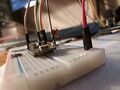
Picture 1: Unsuccessful attempt to put the schematic to the prototyping board

4.2 Soldering to a permaboard
So I went all in and soldered everything together.
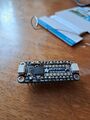
Picture 2: Soldered MCP
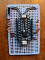
Picture 3: Assembled permaboard from the top
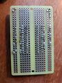
Picture 4: Assembled permaboard from the bottom


On picture 4 you can see how the holes are connected to each other. On picture 3 you see this:
- In the middle the MCP23017 is soldered onto to 13-pin headers (Picture 2) and these again soldered to the board.
- Two additional 13-pin headers are soldered right next to the corresponding pins for external connection via Dupont cables.
- The pins D0, D1 and D2 are soldered with jumpers to the ground (GND) line. This is to get the address 0x20.
- GND is also connected to the ground line, while VIN and Rst goes to the hot line (+5V)
- The longer grey cables connect the two corresponding GND and +5V lines with each other
- On the top left you see a 4-pin header soldered to GND. These are supposed to connect the encoder GNDs. Later on I soldered the same 4-pin header right next to it to the +3.3V line. We'll come back to this later.
- The 12 light brown thingies are the decounce capacitors. They connect each signal line of the encoders to GND (see Parts section above)
4.3 Assembling
Now everything gets assembled.
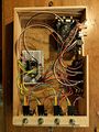
Picture 5: Assembling the parts inside the case is finished

First we need to connect some PI GPIOs to the soldered board. We use the two 13-pin headers next to the MCP23017. Therefore we check the Pi GPIO pinouts.
| From Pi... (Physical Pin Number) | 5V (2) | GND (6) | SDA (3) | SCL (5) | GPIO (36) | GPIO (37) |
| To MCP23017 | VIN | GND | SDA | SCL | Int-A (IA) | Int-B (IB) |
Now we connect the encoders to the respective pins, in that version labeled A0-A7; B0-B7. You can basically chose every combination (see section "wiring setup"), but we'll use this, because it's convenient for cable lead:
| MCP23017 | B4 | B5 | B6 | B0 | B1 | B2 | A4 | A5 | A6 | A0 | A1 | A2 |
| Encoders | Enc1 CLK | Enc1 DT | Enc1 SW | Enc2 CLK | Enc2 DT | Enc2 SW | Enc3 CLK | Enc3 DT | Enc3 SW | Enc4 CLK | Enc4 DT | Enc4 SW |
Additionally we connect all encoder GND to the boards GND line, where we soldered the 4-pin header mentioned above. In picture 5 you see the second 4-pin header soldered to the 5V line already, where we connect the encoder "+" to 5V. Why is that?
I happened to have ordered encoders mounted on a PCB, don't ask why. This includes 10kOhm pull-up resistors (don't ask why). The two options were to desolder these resistors, cut their lines or just power the encoders. I chose the latter option. Without connecting them to 5V they actually worked, but very clumsy, unreliable and sometimes triggering other actions than intended.
5 Wiring setup
6 Building a case
7 Further plans
I already have some parts lying around if ever I find time to add these to the build and also find the courage to disassemble a working device. These include:
- More MCP23017 expanders for physical buttons
- 20 Capacitive buttons to mount under the thin wooden top to act like the 20 V5 buttons.
- A TOF sensor for altering parameters with magic air gestures
- Some plywood to build a more sturdy case
- Probably moving the audio HAT off the PI with a 40-pin GPIO extention cable for better air ventilation