Difference between revisions of "Building a Zynthian Box using an official Kit"
| Line 373: | Line 373: | ||
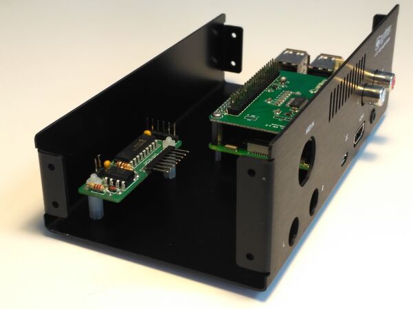
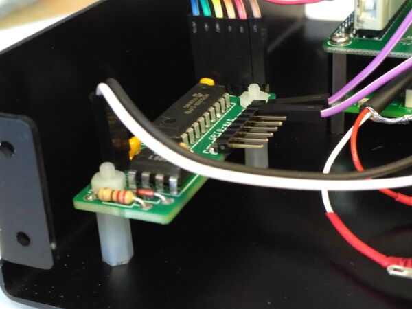
[[File:Zynthian_mounting_2in1_top.jpg|600px]] | [[File:Zynthian_mounting_2in1_top.jpg|600px]] | ||
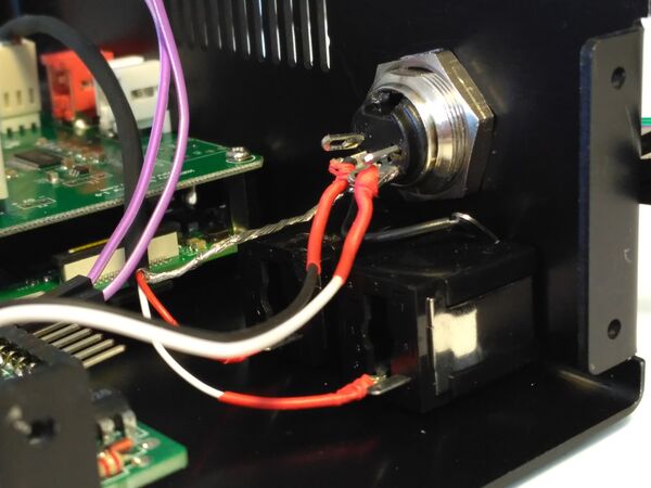
| − | Also connect the DIN-5 connector (MIDI-IN) to the 2in1 module. It's the 2-pin connector labeled as MIDI-IN. | + | Also, if you haven't done this before, connect the DIN-5 connector (MIDI-IN) to the 2in1 module. It's the 2-pin connector labeled as MIDI-IN. |
[[File:Zynthian_mounting_2in1_case.jpg|600px]] | [[File:Zynthian_mounting_2in1_case.jpg|600px]] | ||
Revision as of 16:22, 18 January 2017
1 Introduction
This tutorial is mainly intended for those who are building a Zynthian Box using one of the official kits that i offer here:
Getting a Zynthian Kit
Anyway, it's quite detailed and can be used as a guide to build a custom Zynthian Box from scratch. Of course, you will have to be creative if you want to do it in that way ;-)
2 Some definitions
2.1 Zynthian
It's an open project with the goal of creating an Open Synth Platform based in Free Software and Open Hardware Specifications & Designs (when available). It's a community-driven project. If you are here, probably you already know all this ;-)
2.2 Zynthian Software
The Zynthian Software stack consist of:
+ GNU Linux Operating System: Raspbian Jessie (Minibian is used in the last SD images)
+ Jack Audio Daemon
+ MOD-HOST + MOD-UI software, from ModDevices (github repositories)
+ A collection of standalone Synth Engines & LV2 Plugins (see Supported Synth Engines & Plugins)
+ Zynthian User Interface (github repository)
All the software used by Zynthian is Free Software (free as in freedom, not as in free beer) and it's covered by the GPL license or similar. If you don't know what i'm talking about, please, take a look to this:
What is Free Software?
The easiest way of getting the software is downloading the last official SD image from here:
Download Zynthian "Gorgona" SD-image
This SD-image include all the zynthian software properly configured and ready to use. Plug and play! ;-)
After downloading the SD-image, you have to write it to a SD-card. Depending on your OS you have to choose how to create the SD-card. You need a minimum size of 16GB for the full Gorgona image and 8GB for the Gorgonilla lite image. There is a really good manual for this at this link.
If you prefer, you can build your own SD image following these instructions:
Building the SD Image using the Setup Script
2.3 Zynthian Box
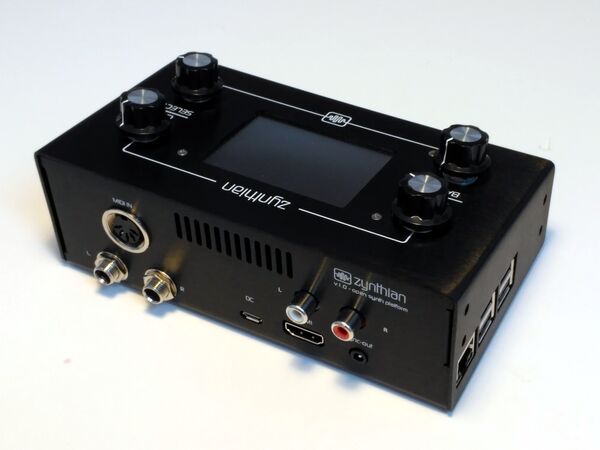
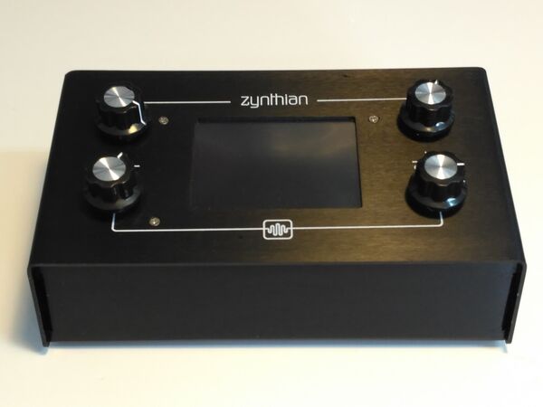
A Zynthian Box is a hardware device, a small digital computer designed to run the Zynthian Software. Currently it's based in the Raspberry Pi platform, but it could be easily adapted to other computer platforms.
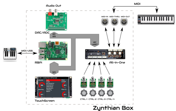
This is a sketch with the main blocks of the official Zynthian Box:
In the project's repositories you will find all the electric schemes, PCB specifications, Herber files, etc. to build your own Zynthian Box from scratch:
- Zynthian Hardware Repository
- Zynthian Case Repository
The official version is the canonical reference. Of course, you don't have to build the official version. You can build your customized Zynthian Box modifying and improving what you want. If you do so, some feedback would be very appreciated ;-)
2.4 Zynthian Kit
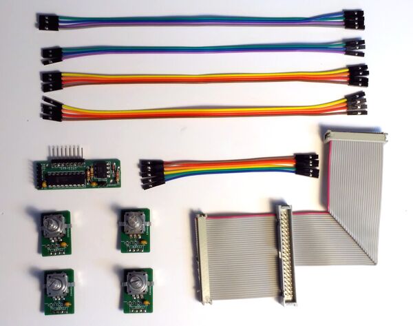
A Zynthian Kit is a set of specific and generic electronic modules designed or picked for building a Zynthian Box. This tutorial refers to the official Zynthian Kit, that is composed of these specific parts:
+ 4 x Controller Modules (rotary encoder + switch)
+ 1 x 2in1 Module (GPIO expander + MIDI IN)
+ 1 x Main ribbon bus cable
+ Set of Dupont color-wire connectors
and these generic parts:
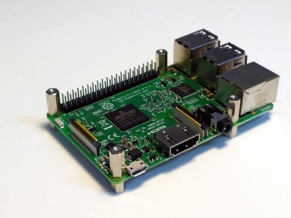
+ 1 x Raspberry Pi 2/3
+ 1 x Hifiberry DAC+ (also pro & lite)
+ 1 x Adafruit PiTFT 2.8' ScreenTouch (or clonic)
Of course, other arrangements and combinations are possible and some community members are working on them:
- A build with variations, by vagnscott
- Another Wiring, by Imager
2.5 Zynthian Case
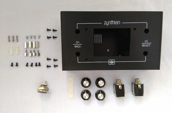
It's the enclosure used to put on all the parts. Again, this tutorial refers to the official Zynthian Aluminum Case, that is designed to be used in conjunction with the official Kit.
This case is available as a kit, including all the needed connectors, knobs, bolts & nuts:
If you intend to use a different soundcard or display, probably it won't fit the case and you will have to modify it. Of course, you can build your own customized case. Here you can find some examples from the community:
- Zynthian Enclosures
- Success Cases
3 Building the Zynthian Kit parts
3.1 Prerequisites
Building your own Zynthian Box is not very difficult, but you will need all your attention, some basic tools and a few skills. Read the instructions and observe the detailed photos carefully. If you get in trouble you can ask the community:
https://discourse.zynthian.org
3.1.1 Required Skills
For building the hardware you should have the following basic competences:
+ Soldering
+ Basic understanding of reading basic electronic circuit diagrams
+ Enjoyment of work with electronic hardware and parts
3.1.2 Tools
And this is the list of required and recommended tools:
+ Soldering iron
+ Tin-solder
+ Wire-cutter
+ Small Pliers
+ Screw drivers
+ PCB holder for soldering (very recommended!)
+ Small iron brush (very recommended!)
+ Magnifiying glass (recommended)
+ A vice (recommended)
+ A hand saw for metal (recommended)
+ Multimeter (recommended!)
3.2 Some general recommendations
1. Be careful with your fingers. Your body can hold a good amount of static electric charge. Under some circumstances that charge can be drained through some of the components that you are handling and this could break the component. Try to hold the PCBs by the borders and discharge your body frequently touching some "ground" with your fingers.
2. Before soldering, please, check that you are soldering in the right side of PCB, also that components orientation is correct (ICs, diode)
3. When soldering, always avoid overheating. Electronic components doesn't like overheat! This is specially important when soldering the big connectors in the HifiBerry soundcard and the PiTFT touchscreen. If you overheat the circuit, probably you will break some electronic component and you will end with a dead board. I recommend to use a fan while soldering. If not, you can use your mouth ;-) Also, don't solder the contacts in order. It's better to jump from one to another in the oposite corner. If you are not sure of your soldering skills, please, take your time and do some practice with inexpensive components and prototyping board.
4. After finishig the soldering, brush smoothly all the contacts. You may use a small iron brush. After that, blow over the circuit to remove any remaining tin.
5. Inspect visually all the soldered contacts. You could use a magnifying glass for verifying that every soldered pin looks good. If you are not sure, perhaps you could add more tin or re-solder the pin. Also, you could use a multimeter for testing the dubious contacts.
6. And of course, double-check everything! Assembling and wiring process are prone to errors. Don't be too confident ;-) Re-check component's orientation (ICs and diode), wiring, etc.
3.3 Assembling the Controller Modules
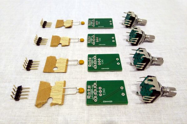
The controller module kit is composed of:
+ 4 x controller PCBs
+ 4 x rotary encoders with switch (PEC11R-4215K-S0024)
+ 4 x ceramic capacitor 100nF (C1)
+ 4 x 4-pin-row male connector (angle)
This components are used to build the 4 controller modules that form the input side of the physical Zynthian User Interface. Each controller embed an incremental rotary encoder and a switch, so 4 wires are needed for connecting it with the RBPi GPIO.
These are the steps for building one module:
0. Be sure that you have readed and understanded these recommendations.
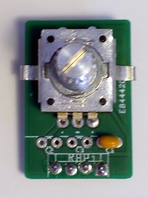
1. Bend the encoder's securing tabs to 75º, so you can insert it in the upside of the PCB (the labeled side!). Please, be very careful when bending the tabs as the encoder case is quite fragil and could be deformed. I recommend to use small pliers and not reaching to 90º.
2. Place the capacitor in the C1 position (the most right!)
3. Solder the encoder and capacitor carefully.
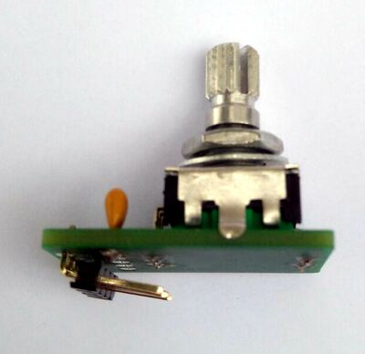
4. Place the pin-row connector in the downside of the PCB, with the angle pins facing inwards (look the photo!)
5. Solder the pin-row carefully.
6. Bend the pin-row outwards a little bit, like shown in the photo. You can use a screw-driver or similar to do it.
7. Use the pliers to close the tabs again, trying to "catch" the PCB.
You have to build 4 controller modules, so you to have to repeat the steps 4 times.
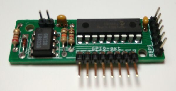
3.4 Assembling the 2in1 Module
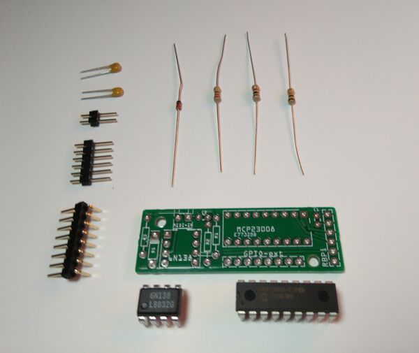
The 2in1 module kit is composed of:
+ 1 x 2in1 PCB
+ 1 x opto-coupler 6N138 => 8 pins IC
+ 1 x dioode 1N4148 (D1)
+ 1 x resistor 1K (R1) => red-black-brown
+ 1 x resistor 10K (R2) => orange-black-brown
+ 1 x resistor 220 (R3) => red-red-black
+ 1 x MCP23008 => 18 pins IC
+ 2 x ceramic capacitor 100nF (C1, C2)
+ 1 x 8-row-pin male connector (angle)
+ 1 x 6-row-pin male connector
+ 1 x 2-row-pin male connector
These are the steps for building the 2in1 module:
0. Be sure that you have readed and understanded these recommendations.
1. Place all the components in the upside of the PCB (the labeled side!). Put attention to the orientation of the ICs and diode.
2. Solder the components carefully. Always avoid overheating!
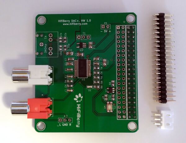
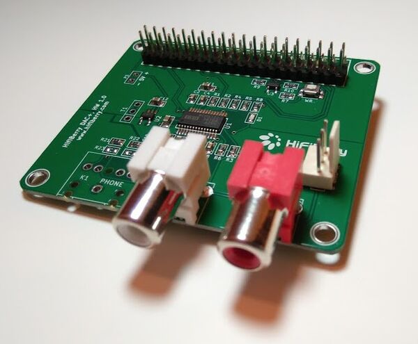
3.5 Tweaking the HifiBerry DAC+ soundcard
If you are using the HifiBerry DAC+ soundcard (also lite & pro versions), you should add 2 extra connectors to the board:
+ 40 row-pin GPIO male connector, for connecting the main ribbon bus cable
+ 3 pin header connector, for connecting the extra audio line-out Jack connectors
Both connectors must be placed on the top side of the board, so you should solder the contacts on the bottom side.
WARNING! Soldering the big 40-pin connector can be difficult if you don't have enough practice. Please, before starting be sure that you have readed and understanded these recommendations.
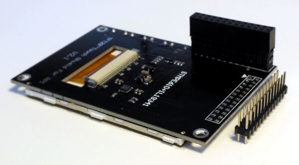
3.6 Tweaking the PiTFT 2.8' TouchScreen
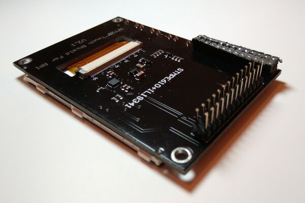
If you are using the Adafruit PiTFT 2.8' TouchScreen (or a clonic version) in a standard mounting (standard main ribbon bus and case size), is highly recommended to use the side 26-pin male connector, not the bottom female connector. The main ribbon bus is designed to use the side 26-pin male connector, and the case mounting will be easier if you do so.
3.6.1 Original Adafruit TouchScreen
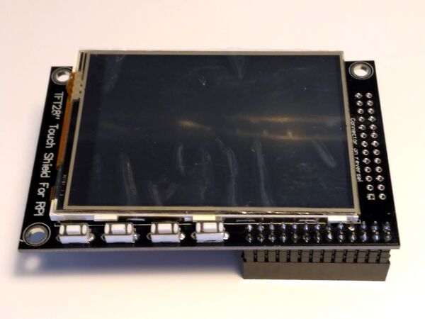
If you have an original Adafruit PiTFT 2.8' TouchScreen, probably you have both connectors soldered in the board, so you don't need to solder anything. Anyway, the bottom female connector is quite annoying when trying to close the case, so perhaps you want to remove it using a saw. If you do so, i also recommend to use a vice.
3.6.2 Clonic TouchScreen
If you have a clonic PiTFT 2.8' touchscreen, probably you don't have the side 26-pin male connector soldered on the board, so you should solder it by your own. Also, normally the female connector in the clonic versions is higher that in the original and more annoying yet, so, you will want to remove it with a saw. If you do so, i also recommend to use a vice.
After removing the female connector, the side connector must be soldered. Note that you have to place it on the bottom side of the board, so you should solder the contacts on the top side.
WARNING! Soldering the 26-pin connector can be difficult if you don't have enough practice. Please, before starting be sure that you have readed and understanded these recommendations.
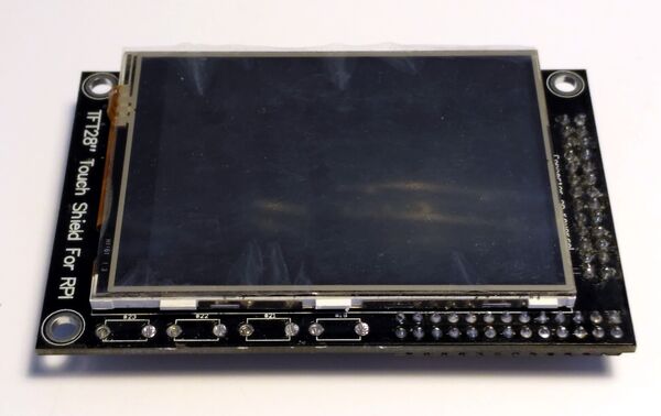
Frequently, clonic PiTFT touchscreens have 4 switches welded on it. These switches can be annoying when holding the display to the case. If the switches remain pressed after mounting, then it will cause problems as are connected to the GPIO and will conflict with the controller modules. The switches are easily pulled out by slighty turning each switch parallely to the board with a pair of pliers.
3.7 Other Soundcards and Displays
If you are using a different soundcard or display, you'll have to see the best way to integrate it. If you do so, please, don't forget to give good feedbak in the forum or here, in the wiki.
In the forum you can see what other users have done, and of course, don't doubt to ask whatever you want!
https://discourse.zynthian.org/c/building-zynthian
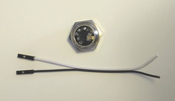
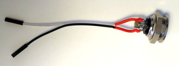
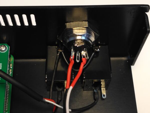
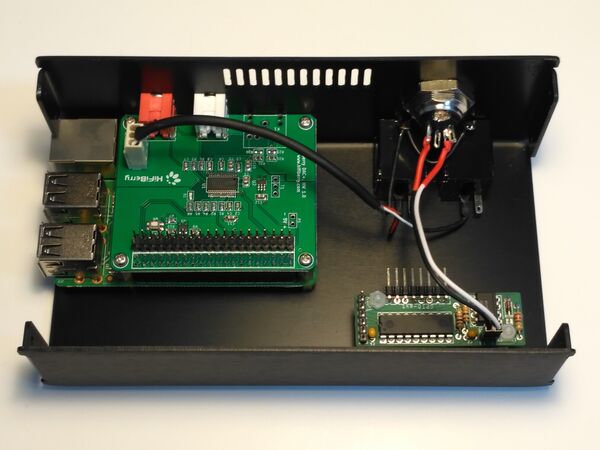
3.8 Building the MIDI-IN connector
Before mounting the MIDI-IN connector into the case we will solder the needed wires. Doing it in that way is rather more comfortable than trying to solder inside the case with all the wiring mess.
If you want, you can protect the contacts using heat-shrink sleeve (the red sleeve pieces in the photo). In that case, remember to insert the sleeve pieces before soldering ;-)
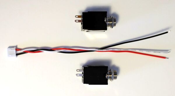
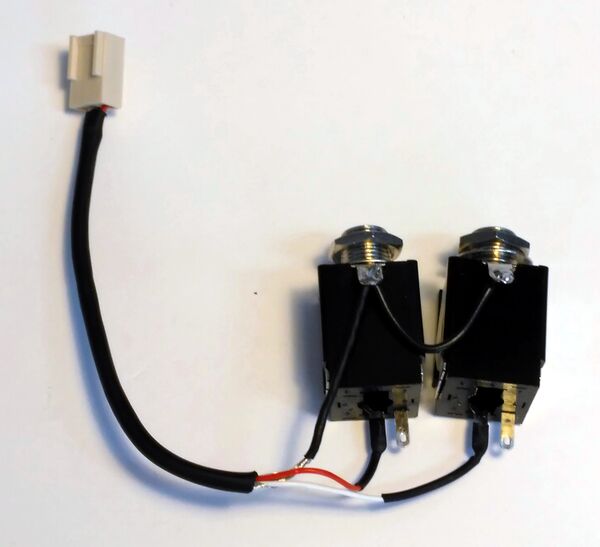
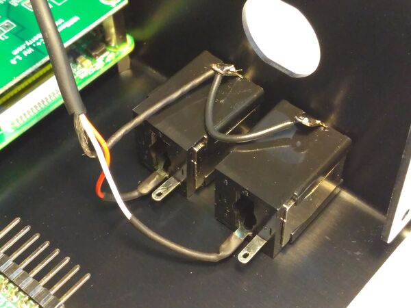
3.9 Building the JACK Audio-Out connectors
In the same way, before mounting the Jack connectors into the case we will solder the needed wires. You can use heat-shrink sleeve too.
4 Case Mounting
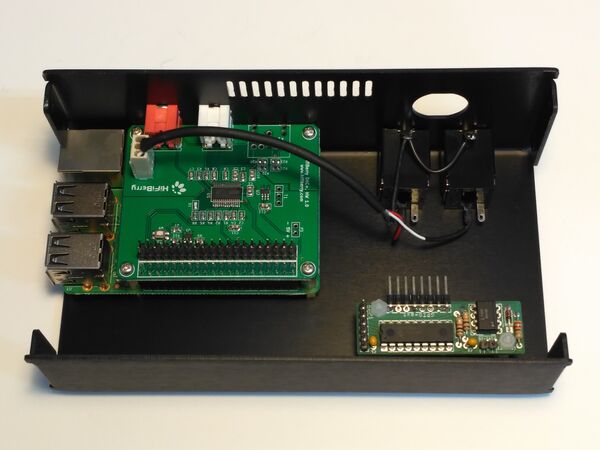
4.1 Assembling the Main Computing Block
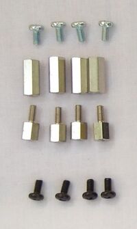
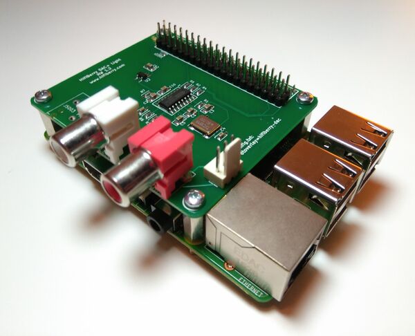
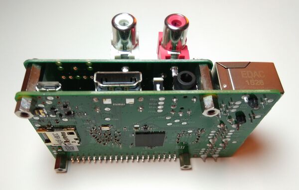
The main computing block is composed by the RBPi and the HifiBerry soundcard, and shouold be assembled using the next set of separator & bolts:
For easier assembling, you should follow the next steps:
1. fix the 2x4 separators to the RBPi. The bigger one must be on top and the smaller one on bottom.
2. insert the Hifiberry soundcard in the RBPi.
3. screw the 4 bolts on top of the HifiBerry.
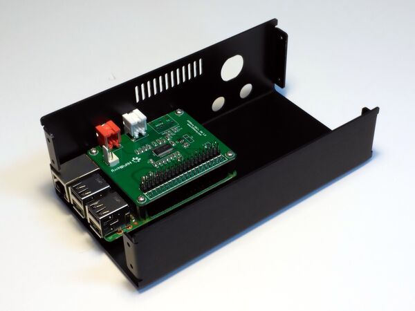
4.2 Holding the Main Computing Block
4.3 Holding the 2in1 module
4.4 Holding the Jack connectors
4.5 Holding the MIDI-IN connector
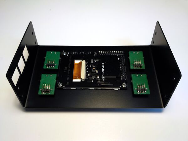
4.6 Holding the ScreenTouch
4.7 Holding the Controllers
4.8 Stick the rubber feet
5 Connecting everything
5.1 Connect the Dupont Wires to the Main Ribbon Bus
5.1.1 Controller Module 4-pin Dupont Wires (x 4)
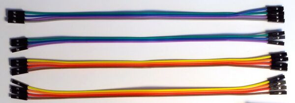
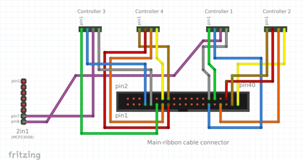
Take the 4 x "20cm 4-pin Dupont Connector Wires". These wires are used to connect the 4 controller modules to the RBPi GPIO:
You have to connect it to the middle male connector of the Ribbon Bus Cable following the next scheme:
You can leave disconnected the two purple wires. It's more comfortable to connect it to the 2in1 module after pluging the Main Ribbon Bus to the RBPi.
Note: While connectig the wires, the red wire of the Main Ribbon Bus must be at left. The red wire is ALWAYS the #1!
5.1.2 2in1 Module 6-pin Dupont Wire
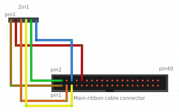
Next, you take the "10cm 6-pin Dupont Connector Wire". This is used to connect the 2in1 module to the RBPi GPIO:
You have to connect it to the middle male connector of the Ribbon Bus Cable following the next scheme:
Note: While connectig the wires, the red wire of the Main Ribbon Bus must be at left. The red wire is ALWAYS the #1!
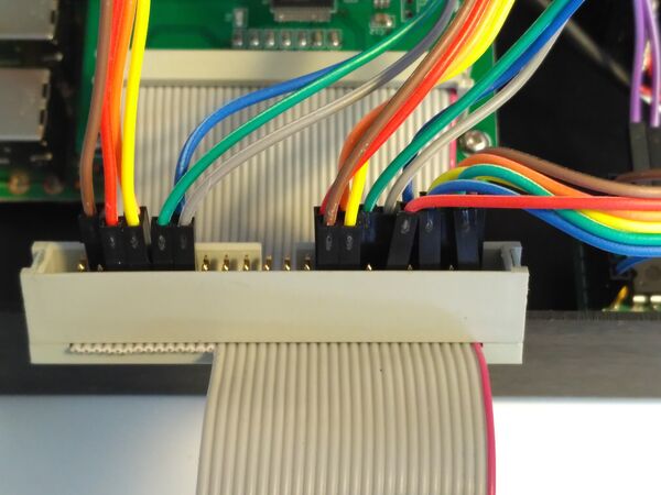
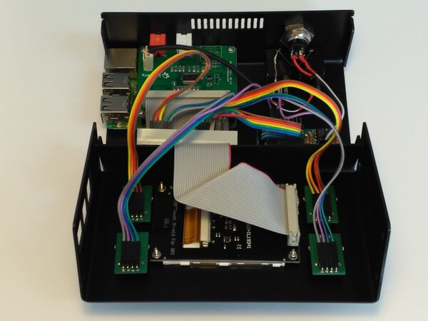
In that point you should have something like this:
5.1.3 Connect the Main Ribbon Bus to the RBPi
It's time to connect the Main Ribbon Bus to the RBPi GPIO. When looking to the case from the front side, the red wire must be in the right, like in the photo:
PHOTO NEEDED HERE!!
It's also time to connect the two purple wires to the 2in1 module if you haven't done before.
5.2 Connect the Controller Modules (x4)
This step is a bit tricky. Remember that, if you followed the instructions before, you have soldered the pin-rows in the bottom side of PCBs, so numbering is reversed when looking from bottom. You can use a little trick: if you rotate the PCB 180º, then numbering is "left to right" again ;-)
So you should look at your controller modules from bottom side and with the pin-row on the top of PCB!
Note: Some encoders have reversed pin ordering, so, if you buy the encoders by yourself, perhaps you have to change A and B pins (brown<=>red, green<=>blue).
5.3 Connect the 2in1 Module
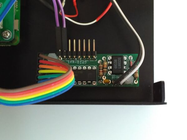
Connect the 6-pin dupont wire to the 2in1 module. Numbering is from left to right (top to bottom in the photo) and pin 1 is the brown wire:
Also, if you haven't done this before, connect the DIN-5 connector (MIDI-IN) to the 2in1 module. It's the 2-pin connector labeled as MIDI-IN.
5.4 Connect the Jack connectors
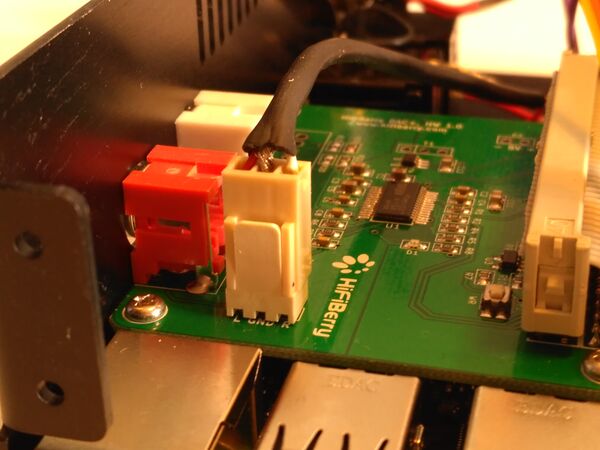
And finally, connect the Jack connectors to the auxiliar on-board audio-out connector in the HifiBerry soundcard. This is the 3-pin connector that you soldered before:
6 Testing the Zynthian Box
And that's all. Your Zynthian Box is almost ready to boot. I recommend that you double-check everything before trying to boot.
6.1 Double-check part's assembling and wiring
It's easy to make a mistake while assembling the parts or connecting the wires. Some errors can be dangerous for the electronic components (short-circuits, some specific bad-wiring combinations) so it's better to be sure that everything is correctly assembled and connected.
6.2 First Boot
When you are pretty sure that everything is in its place, it's time to boot by first time, so:
1. Insert the SD-card with the zynthian image ready to run. If you don't have one yet, read this.
2. Plug the mini-usb power conector. A good 5V micro-usb charger is recommended (> 1 Amp).
These are the stages that you should see while booting:
1. Initially, the display must go white
2. After 5-10 seconds, it will show the Zynthian splash screen
3. After 1-2 seconds, it will go black
4. If you are using a fresh zynthian image, the stages 2 and 3 will be repeated
5. After 5-10 seconds, the zynthian UI will be shown
If you get the Zynthian UI, congratulations!!! You are really close to get it!!
If not, bad luck! Probably you made some mistake during the mounting process. You have to locate and solve the problem(s).
6.3 Test the Controllers
If you get the Zynthian UI, then you should start by testing that your controllers are working OK.
1. Push the 'SELECT' controller. You should get into the 'Engine Selection' screen.
If it doesn't works, try pushing the 'LS' controller. Perhaps you have cross-wired the 3 & 4 controllers and in that case, you have to fix the wiring. If it doesn't work, try pushing the other two controllers and rotating the controllers. If something happens, most probably you have reversed the wiring order when connecting the controllers, or perhaps you have changed some wires while connecting the main ribbon bus. Double-check the wiring again.
2. Rotate the 'SELECT' controller to select the engine you want to start.
The selector must go down when rotating clockwise and go up when rotating counterclockwise. If the rotation sense is reversed, you should check the wiring.
3. Push 'BACK'. You should get into the 'Admin' screen. Push 'BACK' again to return to the 'Engine Selection' screen.
4. Select the ZynAddSubFX engine, select channel #1, bank and instrument. You should get into the 'Instrument Control' screen:
CAPTURE NEEDED HERE
5. Rotate every control to test that it works and that the rotation sense is correct.
If some controller doesn't work correctly, check the wiring again. You could try to figure what is happening by analizing the observed behaviour.
6. Push 'LS' to get into the 'Load Snapshot' screen. Push 'LS' again to 'Save Snapshot'. Push 'BACK' to return to the 'Instrument Control' screen.
7. Push 'CH' to jump to the 'Channel List' screen.
If everything works but 'LS' and 'CH' switches, then probably you have some wiring problem in the 2in1 module. Check the wiring again ;-)
Finally, if you can't fix the problems, you could try to login into the system and run some testing program from the command line:
# /zynthian/zyncoder/zyncoder_test
or reading directly the GPIO:
# gpio readall
etc.
6.4 Test the Audio Output
1. Connect the audio output (RCA or Jack connectors) to your amplifier or auto-amplified speakers.
2. Boot your Zynthian. You should be in the initial 'Load Snapshot' screen.
3. Push BACK twice to get into the 'Admin' screen.
4. Select 'Audio Test' option and push 'SELECT'. You should hear the test audio-track: a nice afrocuban stuff ;-)
5. Push 'BACK' to stop the playing
If you don't listen nothing, please, check the amplifier, speakers, cabling, gain, volume, etc. If nothing works, you have to locate and solve the problem(s).
6.5 Test the MIDI subsystem
1. Connect the audio output (RCA or Jack connector) to your amplifier or auto-amplified speakers.
2. Boot your Zynthian, select FluidSynth engine, channel #1 and 'FluidR3 GM' bank.
3. Push BACK, holding the switch pushed more than 2 seconds. You should get into the 'Admin' screen.
4. Select 'MIDI Test' option and push 'SELECT'. You should hear the test midi-track: a 'Take Five' version ;-)
5. Push 'BACK' to stop the playing
If you don't listen nothing, please, check the amplifier, speakers, cabling, gain, volume, etc. If nothing works, you have to locate and solve the problem(s).
6.6 Test the MIDI-USB inputs
TODO!
6.7 Test the MIDI-IN connector
TODO!
7 Close the Case
Closing the case can be a little bit tricky. Take your time to see how to bend and put the cables.
Finally, screw-drive the 8 bolts for fixing the case, 4 each side.
8 Locating and Solving problems
In this section i will try to give you some tips for locating and solving the problems you may have.
For finding and solving problems, i really recommend to connect a HDMI display to the RBPi. It will give you accurate information during the booting sequence. Also, if you connect a USB keyboard, you can login into the system and get extra information, inspect the logs, etc.
8.1 The display don't go white in the boot stage 1
I recommend you disconnect the controller and 2in1 modules and try to boot again. If the problem persist it's very probable you haven't solder correctly the side 26-pin connector. You should double check the connector and be sure that it's correctly soldered.
8.2 The display don't show the zynthian splash screen in the boot stage 2
In that case, probably the system is not booting correctly. You could try to connect a HDMI display and see if the system is booting. If you can't see the booting sequence, then you should re-burn your SD-card with the Zynthian image. Also, check that your image file is correct by using the SHA1 signature.
9 Technical Reference
Finally, i have included here some detailed schemes and tables. People hacking the standard Zynthian design would find it very useful. Also, if you have some problem and need to "debug", you would find it useful too.
You can find all this info and much more in the project's Hardware Repository.
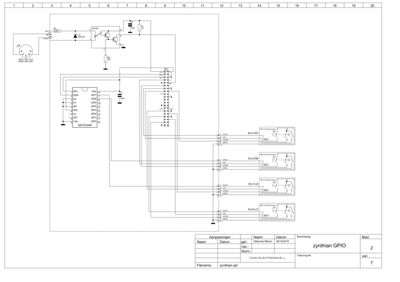
9.1 Electric Scheme
This is the electric scheme of a Zynthian Box, excluding soundcard and display:
Note: The colors indicated in this scheme doesn't match exactly the colors in the schemes above.
9.2 Connection Tables
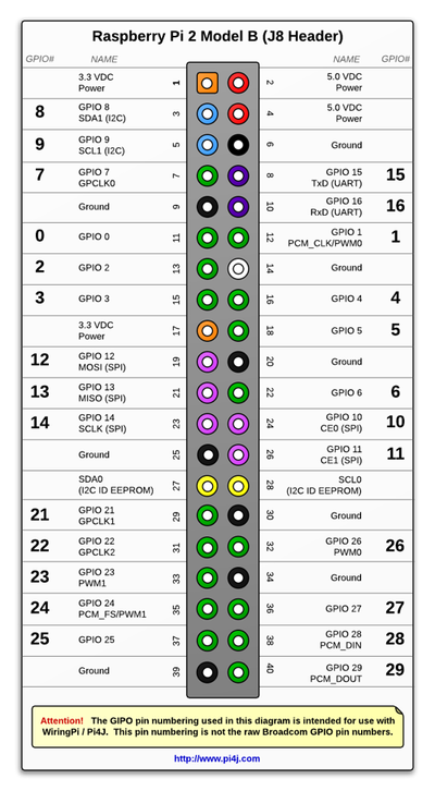
These are the connection tables for the Zynthian Kit modules. Note that the GPIO no. use the WiringPi numbering, not the RBPi official numbering. This numbering is used by the software too:
Controller Module 1
| Wire no. | Function | GPIO no. | Pin on Raspi no. |
|---|---|---|---|
| 1 | Enc2-B | 26 | 32 |
| 2 | Enc2-A | 21 | 29 |
| 3 | Enc2-SW | 07 | GPIO-ext in 2in1 |
| 4 | GND | GND | 30 |
Controller Module 2
| Wire no. | Function | GPIO no. | Pin on Raspi no. |
|---|---|---|---|
| 1 | Enc1-B | 25 | 37 |
| 2 | Enc1-A | 27 | 36 |
| 3 | Enc1-SW | 23 | 33 |
| 4 | GND | GND | 34 |
Controller Module 3
| Wire no. | Function | GPIO no. | Pin on Raspi no. |
|---|---|---|---|
| 1 | Enc2-B | 00 | 11 |
| 2 | Enc2-A | 07 | 7 |
| 3 | Enc2-SW | 08 | GPIO-ext in 2in1 |
| 4 | GND | GND | 9 |
Controller Module 4
| Wire no. | Function | GPIO no. | Pin on Raspi no. |
|---|---|---|---|
| 1 | Enc1-B | 04 | 16 |
| 2 | Enc1-A | 03 | 15 |
| 3 | Enc1-SW | 02 | 13 |
| 4 | GND | GND | 14 |
2in1 <=> RBPi
| Wire no. | Function | GPIO no. | Pin on Raspi no. |
|---|---|---|---|
| 1 | Vdc 3.3V | 3.3V | 1 |
| 2 | RxD | RxD | 10 |
| 3 | I2C SDA1 | 08 | 3 |
| 4 | I2C SCL1 | 09 | 5 |
| 5 | Vdc 5V | 5V | 2/4 |
| 6 | GND | GND | 6/9 |
2in1 <=> MIDI-IN connector
| Wire no. | Function | MIDI-IN pin no. |
|---|---|---|
| 1 | MIDI-IN | 2 (MIDI connector: 2nd from left) |
| 2 | MIDI-IN | 4 (MIDI connector: 2nd from right) |
