Difference between revisions of "Building Zynthian MINI V2"
m (Jofemodo moved page Building Zynthian MINI V2 Guide to Building Zynthian MINI V2) |
Tags: Mobile web edit Mobile edit |
||
| (13 intermediate revisions by 3 users not shown) | |||
| Line 1: | Line 1: | ||
| − | [[File:Zynthian-on-piano-02.png| | + | [[File:Zynthian-on-piano-02.png|600px|right]] |
| − | + | == Introduction == | |
| − | |||
| − | |||
| − | + | Zynthian MINI kit is a cost effective approach to build a zynthian box with similar functionality to v5 kit. | |
| − | * | + | '''NOTE: This is not an official Zynthian kit. It is supported by the community, There is no official Zynthian support for this project but everyone involved in Zynthian (community and core developers) provide ad-hoc support within the forum.''' |
| − | * | + | |
| − | * | + | '''The ''pros'':''' |
| + | |||
| + | * Lower price | ||
| + | * Possibility of inserting a standard RPi-hat | ||
| + | * Smaller format. It's slighty higher than V5, but quite shorter. | ||
| + | * More DIY! You will learn a lot more while building it. | ||
| + | |||
| + | '''The ''cons'':''' | ||
| + | |||
| + | * No audio input | ||
| + | * No amplified headphones output | ||
| + | * No separated TRS audio connectors. No balanced output/input. | ||
| + | * No USB-B connector. Connecting to PC as USB device is more difficult, but still doable. | ||
| + | * Lower performance at medium-high ambient temperature. Overclocking could cause over-heating. The plastic/fiber-glass case can't be used as a heat-sink. | ||
| + | * No RGB LED feedback on push buttons. | ||
| + | * More difficult to assemble. It requires more time and greater skills (i.e. soldering some electronic parts on the PCB) | ||
| + | * Not so robust. Not so cool, but ... heyyy!! MINI-V2 is also quite cool! ;-) | ||
| + | |||
| + | '''The main features of zynthian MINI are:''' | ||
| + | |||
| + | * encoders and switches to control zynthian software in the same way as official zynthian v5 kit, using the MCP23017 i/o extender | ||
| + | * standard DIN-5 connectors for MIDI IN, OUT and THRU | ||
| + | * it uses a I2S DAC for audio out based on PMC5102 chip that is affordable to buy | ||
* does not need any cabling inside for easy assembling | * does not need any cabling inside for easy assembling | ||
* does not need the case to test it but it include design of two type of enclosure | * does not need the case to test it but it include design of two type of enclosure | ||
** simple enclosure that only cover the top and bottom part of the device that can be also produced in the same way as PCBs | ** simple enclosure that only cover the top and bottom part of the device that can be also produced in the same way as PCBs | ||
** full enclosure that can be 3d printed | ** full enclosure that can be 3d printed | ||
| − | * all connectors are easy to reach | + | * all RPi connectors are easy to reach |
| − | + | Zynthian MINI is currently at version 2. Previous version 1 was more similar to official V4 kit with only 4 buttons but it is not maintained anymore. | |
| − | |||
| − | |||
| − | |||
| − | |||
| − | |||
| − | + | == Requirements == | |
| − | To assemble zynthian | + | To assemble zynthian MINI V2 version you will require: |
* PCB that need to be produced based on KiCad design that you can find in [https://github.com/zynthian/zynthian-hw/tree/master/MINI_V2 zynthian hardware] repository. | * PCB that need to be produced based on KiCad design that you can find in [https://github.com/zynthian/zynthian-hw/tree/master/MINI_V2 zynthian hardware] repository. | ||
| − | * | + | * Electronic parts needed to be soldered on the PCB. |
| − | * 5" | + | * 5" Touchscreen (DSI) |
* Raspberry Pi 4 with heatsink | * Raspberry Pi 4 with heatsink | ||
| − | * | + | * ''Optional:'' 3D printed plastic case |
== Assembling the PCB == | == Assembling the PCB == | ||
| Line 147: | Line 162: | ||
* Where to buy: https://www.aliexpress.com/item/1005005835327286.html | * Where to buy: https://www.aliexpress.com/item/1005005835327286.html | ||
17. Push Button | 17. Push Button | ||
| − | * Value: | + | * Value: 13mm |
* PCB label:SW14,SW9,SW16,SW20,SW6,SW10,SW8,SW2,SW17,SW4,SW12,SW19,SW5,SW1,SW13,SW18,SW15,SW7,SW11,SW3 | * PCB label:SW14,SW9,SW16,SW20,SW6,SW10,SW8,SW2,SW17,SW4,SW12,SW19,SW5,SW1,SW13,SW18,SW15,SW7,SW11,SW3 | ||
* Package: push-button | * Package: push-button | ||
| Line 165: | Line 180: | ||
* Package: Jack_6.35mm_Neutrik_NMJ6HFD2_Horizontal | * Package: Jack_6.35mm_Neutrik_NMJ6HFD2_Horizontal | ||
* Quantity: 1 | * Quantity: 1 | ||
| − | * Where to buy: https://www.aliexpress.com/item/4001266094691 | + | * Where to buy: https://www.aliexpress.com/item/4001266094691.html |
| − | |||
| − | |||
| − | |||
| − | |||
| − | |||
| − | |||
=== Soldering === | === Soldering === | ||
| Line 319: | Line 328: | ||
;Legs:These are small legs that are attached (glued) to the bottom part. They are designed to be a separate part from bottom part so that bottom part can be placed to printing bed and sliced without too much additional support. There is one stl file for one leg so you will need to print four of these. | ;Legs:These are small legs that are attached (glued) to the bottom part. They are designed to be a separate part from bottom part so that bottom part can be placed to printing bed and sliced without too much additional support. There is one stl file for one leg so you will need to print four of these. | ||
| − | You can either print this case yourself if you have a printer or give these 4 files to some of your friends that have it and point them to instructions here | + | You can either print this case yourself if you have a printer or give these 4 files to some of your friends that have it and point them to instructions here. |
=== 3D printing instructions === | === 3D printing instructions === | ||
| − | + | Print first the following parts together: top, sd card door and four leg parts by: | |
| − | |||
| − | |||
| − | |||
| − | |||
| − | |||
| − | Print first the following parts together top, sd card door and four leg parts by: | ||
* importing them to printer's slicing software | * importing them to printer's slicing software | ||
* make copy of leg part so taht there are four of them | * make copy of leg part so taht there are four of them | ||
| Line 345: | Line 348: | ||
This will print around 3:30 hours on average commodity printers these days that can easily do 250mm/s such is Elegoo's Neptune 4 or Anycubic Kobra 2. | This will print around 3:30 hours on average commodity printers these days that can easily do 250mm/s such is Elegoo's Neptune 4 or Anycubic Kobra 2. | ||
| − | + | <embedvideo alignment="inline" dimensions="263" service="youtube" description="Timelapse of this first print.">https://youtu.be/5RSKHbG7Gxg</embedvideo> | |
Then print bottom part. Lay bottom side of bottom part onto the printer bed. Use the same settings as for previous parts. Bottom part will be printed much quicker. | Then print bottom part. Lay bottom side of bottom part onto the printer bed. Use the same settings as for previous parts. Bottom part will be printed much quicker. | ||
Latest revision as of 17:52, 27 May 2024
1 Introduction
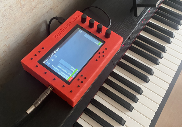
Zynthian MINI kit is a cost effective approach to build a zynthian box with similar functionality to v5 kit.
NOTE: This is not an official Zynthian kit. It is supported by the community, There is no official Zynthian support for this project but everyone involved in Zynthian (community and core developers) provide ad-hoc support within the forum.
The pros:
- Lower price
- Possibility of inserting a standard RPi-hat
- Smaller format. It's slighty higher than V5, but quite shorter.
- More DIY! You will learn a lot more while building it.
The cons:
- No audio input
- No amplified headphones output
- No separated TRS audio connectors. No balanced output/input.
- No USB-B connector. Connecting to PC as USB device is more difficult, but still doable.
- Lower performance at medium-high ambient temperature. Overclocking could cause over-heating. The plastic/fiber-glass case can't be used as a heat-sink.
- No RGB LED feedback on push buttons.
- More difficult to assemble. It requires more time and greater skills (i.e. soldering some electronic parts on the PCB)
- Not so robust. Not so cool, but ... heyyy!! MINI-V2 is also quite cool! ;-)
The main features of zynthian MINI are:
- encoders and switches to control zynthian software in the same way as official zynthian v5 kit, using the MCP23017 i/o extender
- standard DIN-5 connectors for MIDI IN, OUT and THRU
- it uses a I2S DAC for audio out based on PMC5102 chip that is affordable to buy
- does not need any cabling inside for easy assembling
- does not need the case to test it but it include design of two type of enclosure
- simple enclosure that only cover the top and bottom part of the device that can be also produced in the same way as PCBs
- full enclosure that can be 3d printed
- all RPi connectors are easy to reach
Zynthian MINI is currently at version 2. Previous version 1 was more similar to official V4 kit with only 4 buttons but it is not maintained anymore.
2 Requirements
To assemble zynthian MINI V2 version you will require:
- PCB that need to be produced based on KiCad design that you can find in zynthian hardware repository.
- Electronic parts needed to be soldered on the PCB.
- 5" Touchscreen (DSI)
- Raspberry Pi 4 with heatsink
- Optional: 3D printed plastic case
3 Assembling the PCB
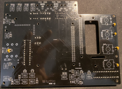
NOTE: Do not be confused that some of the instruction images shown here do not fully align to V2 PCB layout. This is because they are taken with original MINI V2 PCB that had few issues that are now fixed and therefore some small change will be there. Always read the label of the component on the PCB if confused.
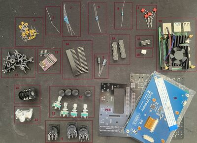
3.1 Components required
1. Capacitors - Electrolytic - Polarized
- Value: 470u 10V
- PCB label: C1
- Package: CP_Radial_D8.0mm_P3.50mm
- Quantity: 1
- Where to buy: https://www.aliexpress.com/item/1005003189675117.html
2. Capacitor - Electrolytic - Polarized
- Value: 100u
- PCB label: C4
- Package: CP_Radial_D6.3mm_P2.50mm
- Quantity: 1
- Where to buy: https://www.aliexpress.com/item/1005003189675117.html
3. Capacitor - Film - Non-Polarized
- Value: 100n
- PCB label: C2,C3,C5,C6,C7
- Package: C_Rect_L7.0mm_W2.0mm_P5.00mm
- Quantity: 5
- Where to buy: https://www.aliexpress.com/item/1005005894912292.html
4. Capacitors - Ceramic - Non-Polarized 100n and 10n
- Value: 100n
- PCB label: C22,C16,C19,C13,C23,C20,C9,C26,C27,C32,C8,C18,C21,C34,C33,C17,C25,C11,C24,C31,C12,C15,C10,C14
- Package: C_Rect_L4.0mm_W2.5mm_P2.50mm
- Quantity: 24
- Where to buy: https://www.aliexpress.com/item/1005002290441861.htm
- Value: 10n
- PCB label: C30,C29,C35,C37,C38,C28,C39,C36
- Package: C_Rect_L4.0mm_W2.5mm_P2.50mm
- Quantity: 8
- Where to buy: https://www.aliexpress.com/item/1005002290441861.htm
5. Diode
- Value: 1N4148
- PCB label: D1
- Package: D_DO-35_SOD27_P7.62mm_Horizontal
- Quantity: 1
- Where to buy: https://www.aliexpress.com/item/32660088529.html
6. MIDI Connectors - PCB mountable
- PCB label: MIDI-OUT-J1, MIDI-IN-J1, MIDI-THRU-J1
- Package: MultiDIN5
- Quantity: 3
- Where to buy: https://www.aliexpress.com/item/1005005773478404.html
7. Resistors
- Value: 220R
- PCB label: R1,R3,R5,R4,R6
- Package: R_Axial_DIN0207_L6.3mm_D2.5mm_P7.62mm_Horizontal
- Quantity: 5
- Where to buy: https://www.aliexpress.com/item/1005005669886834.html
8. Resistor
- Value: 1k
- PCB label: R2
- Package: R_Axial_DIN0207_L6.3mm_D2.5mm_P7.62mm_Horizontal
- Quantity: 1
- Where to buy: https://www.aliexpress.com/item/1005005669886834.html
9. Resistor
- Value: 10k
- PCB label: R8,R7
- Package: R_Axial_DIN0207_L6.3mm_D2.5mm_P7.62mm_Horizontal
- Quantity: 2
- Where to buy: https://www.aliexpress.com/item/1005005669886834.html
10. Digital Optocoupler
- Value: H11L1M
- PCB label: U2
- Package: DIP-6_W7.62mm
- Quantity: 1
- Where to buy: https://www.aliexpress.com/item/32867427644.html
11. Hex inverting Schmitt trigger
- Value: 74HCT14
- PCB label: U1
- Package: DIP-14_W7.62mm
- Quantity: 1
- Where to buy: https://www.aliexpress.com/item/33020259485.html
12. Sound Card PCM5102
- Value: GY-PCM5102
- PCB label: A1
- Package: GY-PCM5102
- Quantity: 1
- Where to buy: https://www.aliexpress.com/item/1005002898278583.html
13. I/O Expander
- Value: MCP23017_SP
- PCB label: MCPMCP23017_SP1, MCPMCP23017_SP2
- Package: DIP-28_W7.62mm
- Quantity: 2
- Where to buy: https://www.aliexpress.com/item/1005005363863079.html
14. 2x20 Pin Header - male and female
- Male:
- PCB label: HAT1
- Package: PinSocket_2x20_P2.54mm_Vertical
- Quantity: 1
- Where to buy: https://www.aliexpress.com/item/4000133266617.html
- Female:
- PCB label: RPi1
- Package: two spacer female 40pin vertical header
- Quantity: 1
- Where to buy: https://www.aliexpress.com/item/4001095693537.html
15. Encoder with a Switch
- Value:
- PCB label: Enc2,Enc4,Enc1,Enc3
- Package: RotaryEncoder_Alps_EC12E-Switch_Vertical_H20mm
- Quantity: 4
- Where to buy: https://www.aliexpress.com/item/1005006142236380.html
16. Encoder Cap
- Value: encoder caps
- PCB label: Encoder caps
- Package: Encoder caps
- Quantity: 4
- Where to buy: https://www.aliexpress.com/item/1005005835327286.html
17. Push Button
- Value: 13mm
- PCB label:SW14,SW9,SW16,SW20,SW6,SW10,SW8,SW2,SW17,SW4,SW12,SW19,SW5,SW1,SW13,SW18,SW15,SW7,SW11,SW3
- Package: push-button
- Quantity: 20
- Where to buy: https://www.aliexpress.com/item/32912263133.html
18. 5" DSI Screen for Raspberry Pi
- Value: Screen
- PCB label: RPI 5" screen
- Package: RPI screen
- Quantity: 1
- Where to buy: https://www.aliexpress.com/item/1005005353135304.html
19. Raspberry Pi 4 4GB with heatsink
- Where to buy heatsink: https://www.aliexpress.com/item/1005004774833369.html
20. 1/4 Stereo jack
- Value: J1
- PCB label: J1
- Package: Jack_6.35mm_Neutrik_NMJ6HFD2_Horizontal
- Quantity: 1
- Where to buy: https://www.aliexpress.com/item/4001266094691.html
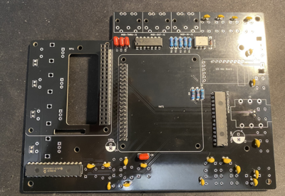
3.2 Soldering
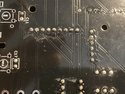
First get PCB and all components sorted by their type. Check their values using digital multimeter to make sure that you have them properly sorted.
Heat up the solder iron and make sure that its tip is clean. If not put some solder on it and clean it with wet sponge. It has to be shiny silver tip.
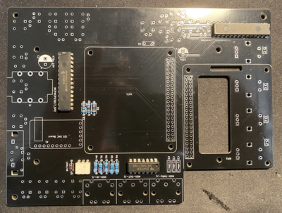
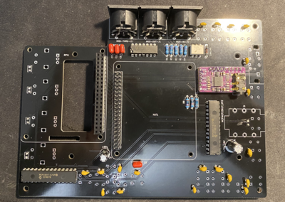
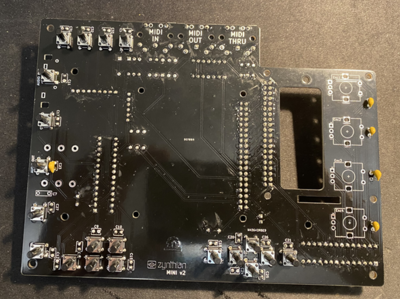
Start by soldering back side of the PCB. Order of soldering is always from smallest to tallest components.
First solder resistors and diode and microchips such as Digital optocoupler (H11L1M), hex inverting schmitt trigger (74HCT14) and I/O Expander (MCP23017). Pay attention to orientation of these microchips.
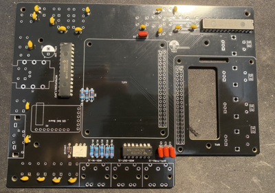
Solder the ceramic and film capacitors at the back of PCB (orientation not important - they are non polarized).
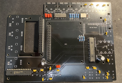
Then solder film and ceramic capacitors at the front (orientation not important - they are non polarized).
Then solder female and male headers
Then solder two electrolytic capacitors. Pay attention to their orientation.
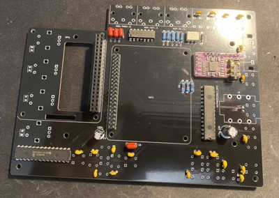
Then solder sound card. First solder male header pins that came with the card and the solder it to PCB board.
Make sure that you have cut sound card pins - they are too long and they will touch the screen if you leave them as it is.
Then solder three MIDI connectors.
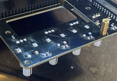
Then solder the switches.
Finally solder the encoders. After soldering them cut any excess wires because that side will be very close to RPI heatsink so any contact to it must be avoided.
You have finished the hard part - soldering. Now you just need to assemble everything together.
3.3 Assembling the PCB for the test
This instruction here are just assembling everything for testing. You should test it before assembling into the case.
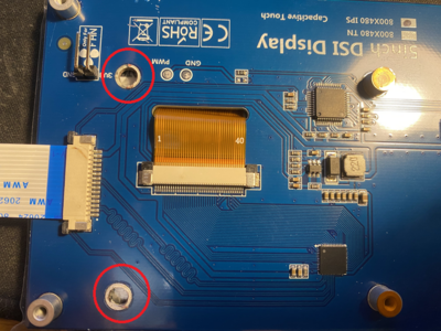
First remove two screen posts that are not necessary and could touch some of the PCB components.
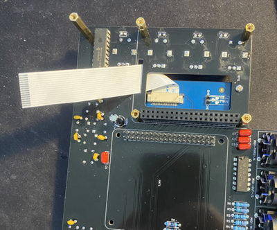
Then connect longer cable that comes with a screen to the screen and attach the screen to PCB.
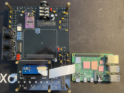
Then screw appropriate hex mounts to PCB for Raspberry Pi. Do not connect Raspberry Pi yet. The type of hex mounts will depend on heatsink that you use. Also connect the screen cable to RPI.
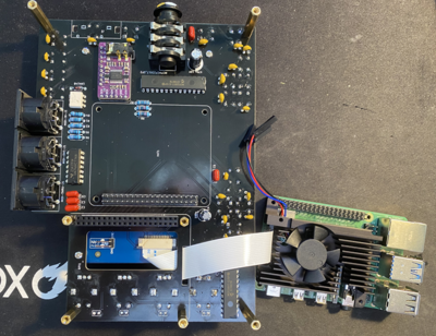
Then connect heatsink to raspberry pi.
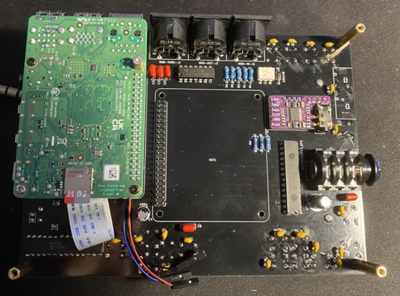
Then connect raspberry Pi to PCB.
4 Configure Zynthian MINI V2 for testing
Download the latest zynthian development branch from os.zynthian.org following this link.
Flash this image to sd card with a size of at least 32GB.
Put the SD card into raspberry Pi and connect zynthian mini to power by connecting USB-C power adapter to Raspberry Pi board. Use correct power adapter.
Optionally you can also connect zynthian mini to network using network cable attached to Raspberry Pi.
Wait for zynthian to start. Zynthian screen will be wrongly oriented, encoders and their push button will not work. Also none of 20 additional push buttons will work. For all this to be configured we need first to get all latest software updates that will also include required options to configure zynthian mini v2.
4.1 Connect to zynthian web UI to update zynthian software
If you have not connected zynthian to your network using network cable you will need to configure zynthian wifi first. You can do this on the screen even though screen is wrongly oriented by
- touching the top corner of the screen
- selecting admin option
- selecting wifi enable option
- selecting your network
- entering your wifi password
You will need to find out zynthian IP address by long touching top left corner of the screen where it says "Mixer" which will open the admin page and then scroll down to Network info. Select network info where you will be able to see IP address if zynthian is properly connected to your network.
Open browser on another computer and type zynthian IP addrese into browser's address bar. You will be prompted to login to zynthian web configuration UI. Oram default password is "opensynth".
4.2 Update zynthian oram software
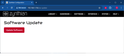
After loging to zynthian web configuration UI click on "Software" from top navigation bar and click on "Update".
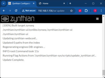
Wait until the software is updated. You need to make sure that it says "Update Complete" at the end of the logs.
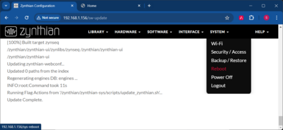
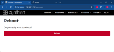
Once you have updated the software restart the zynthian by clicking "System" option from top navigation and then selecting "Reboot".
4.3 Configuring zynthian mini v2 as a kit
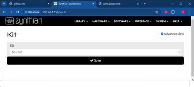
Once zynthian oram software is updated and zynthian restarted you can configure most of zynthian MINI hardware simple by selecting the Mini V2 Kit. To do that click on "Hardware" from top bar navigation and select Kit option. On this screen select "Mini V2" kit and Save.
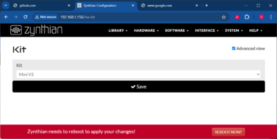
Once it is saved you will need to click on restart at the bottom of the Save page.
Now all hardware is configured and should work properly. Screen orientation should be correct, proper sound card selected, all encoders and switches should work properly. What is left is just few screen UI adjustments.
4.4 Adjusting UI for Zynthian layout
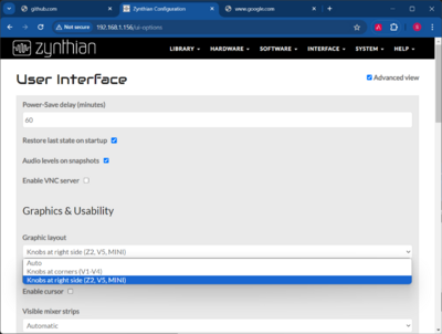
Zynthian Mini V2 has all encoders on the right and therefore corresponding UI widgets need to be always on the right instead of left and right that is default configuration. Also by default cursor is visible which is not necessary when there is a touch screen. To set these two options click on "Interface" from top navigation bar and select "UI options". On this screen set the field called "Graphic layout" to "Knobs at right side (Z2, V5, MINI)" and also deselect "Enable cursor" option.
Restart the Zynthian mini after the all configuration is done.
Once everything is configured and working it is a time to put zynthian into the enclosure.
5 Assembling Zynthian MINI V2 into 3d printable enclosure
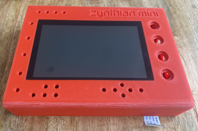
Zynthian MINI V2 3D printable case consists of four parts:
- Top
- This is most important part because it encloses all internal parts together. You can print just this part and have zynthian mini much more secured then just standing on stand offs.
- Bottom
- Bottom part closes the bottom of the case and comes with opening for the SD Card.
- SD card door
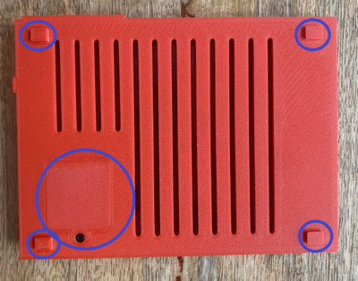
- This is a SD card door that is attached to bottom part for easy access to zynthian's raspberry pi SD Card.
- Legs
- These are small legs that are attached (glued) to the bottom part. They are designed to be a separate part from bottom part so that bottom part can be placed to printing bed and sliced without too much additional support. There is one stl file for one leg so you will need to print four of these.
You can either print this case yourself if you have a printer or give these 4 files to some of your friends that have it and point them to instructions here.
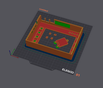
5.1 3D printing instructions
Print first the following parts together: top, sd card door and four leg parts by:
- importing them to printer's slicing software
- make copy of leg part so taht there are four of them
- lay the top side of top.stl part onto the printer bed
- lay the top side of sd-card-door.stl part onto the printer bed
- leave legs as they are imported
- arrange all part nicely aso that they do not overlap (you can use slicers auto arange feature)
- set "zynthian mini" logo with "no support" instructions - there is not need to add support to these letters (it depend on the slicer how you do that but typically you can do this by painting them with no support indicator)
- slice it with 15% infill and with support
- do you standard preparation of you printer before prinitng (e.g. bed level, z offset etc)
- upload the print instructions from slicer and start printing
This will print around 3:30 hours on average commodity printers these days that can easily do 250mm/s such is Elegoo's Neptune 4 or Anycubic Kobra 2.
Then print bottom part. Lay bottom side of bottom part onto the printer bed. Use the same settings as for previous parts. Bottom part will be printed much quicker.
5.2 Assembling all parts into 3D printed case
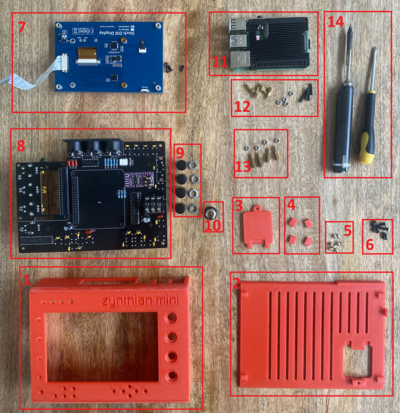
Here is the list of all components required to assemble zynthian mini V2 into the case:
- Case Top part
- Case Bottom part
- Case SD Card door part
- Case legs parts
- brass heat set inserts (quantity 8) - M2.5xL4xOD3.5 - can be purchased here
- screws for brass heat set inserts (quanity 8) - M2.5, 6mm - can be purchased here
- 5" DSI screen and its screws - can be purchased here
- zynthian MINI V2 PCB - check instructions above how to assemble it
- enncoder caps (quantity 4) and nuts - check PCB components required above where to buy it
- Neutrik 1/4 stereo connector cap - can be purchased [1]
- raspberry pi 4 with heatsink
- raspbery pi posts and their screws - their size depend on heatsink - the standard zynthian MINI V2 PCB build recommends two spacers connector which is 16mm long so that there is enough space for raspberry pi to cool - therefore if heatsink is 7mm then raspberry pi posts need to be 9mm (7mm+9mm=16mm)
- HAT posts (quantity 4) - 11mm standard.
- Tools required - soldering iron for inserting heat set inserts and small phillips screw driver
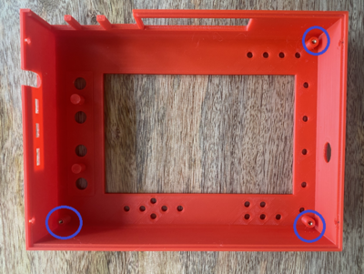
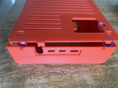
5.3 Insert 3 heat set inserts into top and 5 into bottom part
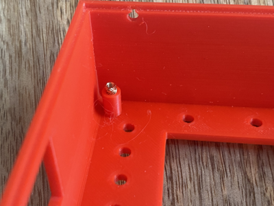
Heat set inserts are easily inserted using soldering iron. The first you need to put insert into the position like this:
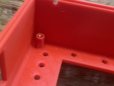
Then put soldering iron on top of the insert and gently pushed it inside the hole so that it is fully in like this:
Here is the location of holes where heat set inserts need to be inserted for top part
Here is the location of holes where heat set inserts need to be inserted for bottom part
There are other 2 holes for heat set inserts on the other side of the bottom part.
5.4 Put screen inside the top part
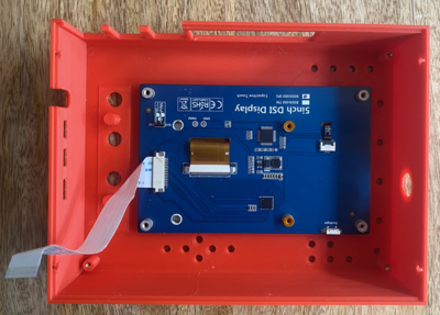
First attach the cable to the screen. Then lay down the top part face down on the flat surface and put the screen through the screen opening like this:
Check that screen top is flat with top part face:
Screen opening on top part is snag enough to keep screen in place while you are moving the top part even though screen is not yet fixed to anything. Don't be confused that screen is up side down - this is intentional so that screen cable connector is close to the raspberry pi connector.
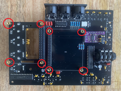
5.5 Screw raspberry pi posts and HAT posts to the PCB
Now screw raspberry pi posts and HAT posts to PCB. Here is their locations on PCB:
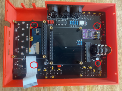
5.6 Put PCB into the case and attach the screen screws
Here is the location of screen screws on the PCB:
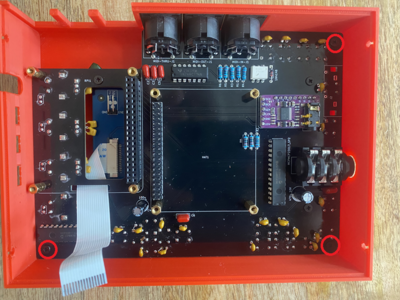
5.7 Screw PCB to the case
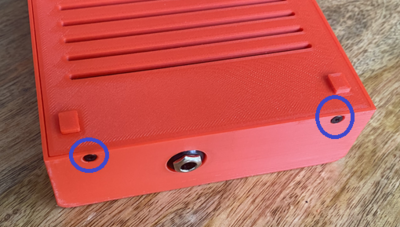
Here is the location of PCB screws that need to be screwed into the case:
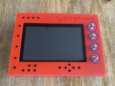
5.8 Screw encoder screw nuts
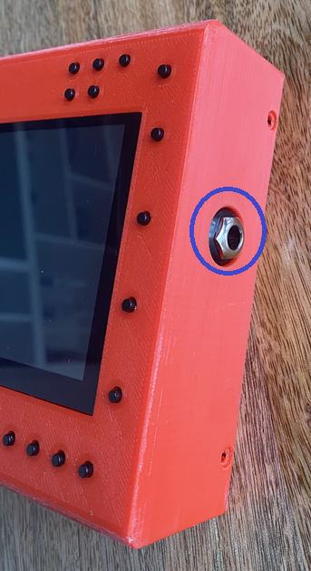
5.9 Screw Neutrik connector nut
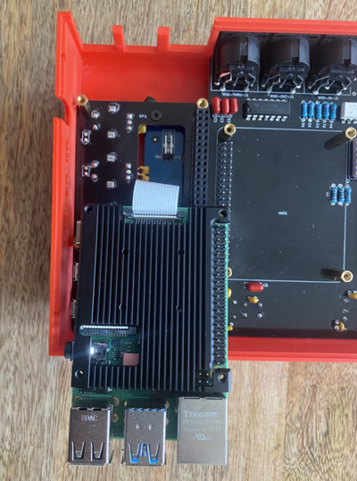
5.10 Attach screen cable to the raspberry pi
5.11 Connect raspberry pi to the PCB
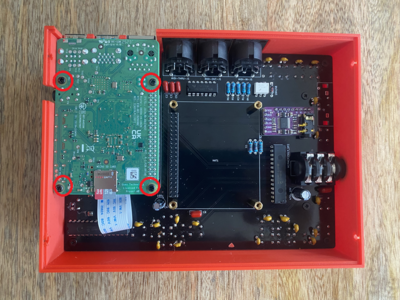
Here is location of raspberry pi post screws that need to be screwed
