Difference between revisions of "Build a Zynthian"
| (53 intermediate revisions by 5 users not shown) | |||
| Line 1: | Line 1: | ||
| − | = How to build a Zynthian | + | = How to build a Zynthian = |
| − | ''' | + | '''This manual is currently in development!''' |
| − | ''' | + | == Disclaimer == |
| + | '''No guarantee for nothing. You do everything on your own risk!''' | ||
| − | == | + | == Prerequisites == |
| − | Want to join the Zynthian community? No problem! | + | Want to join the Zynthian community? No problem! Building your own Zynthian is not very difficult. If you get trouble you can contact us at [mailto:support@zynthian.org support@zynthian.org] or via the blog [http://blog.zynthian.org http://blog.zynthian.org]. |
| − | === | + | === Required competences === |
For building the hardware you should have the following competences: | For building the hardware you should have the following competences: | ||
* Soldering | * Soldering | ||
| − | + | * Basic understanding of reading electronic circuit diagrams | |
| − | * Basic | + | * Enjoyment of work with electronic hardware and parts |
=== Tools === | === Tools === | ||
| Line 29: | Line 30: | ||
=== Bill of Material === | === Bill of Material === | ||
| − | Here is a list of hardware you need. I | + | Here is a list of the hardware components you will need to build the Zynthian device. I also provided links to my suppliers and the prices I paid for the components in February 2016. I bought everything from Germany, so all descriptions are in German and prices are in EUR. If you live in another country maybe you'll get things even cheaper. |
{| class="wikitable" | {| class="wikitable" | ||
| Line 87: | Line 88: | ||
'''Notes:''' | '''Notes:''' | ||
| − | * Pos. 19-22 | + | * Pos. 19-22 were ordered directly from Zynthian. |
| − | * There is no case in this BoM - You | + | * There is no case in this BoM - You can build your own or ask Zynthian. |
| − | * | + | * Total price was 200,27 € (plus shipping). |
[[File:Zynthian_Parts.jpg|600px]] | [[File:Zynthian_Parts.jpg|600px]] | ||
| − | == | + | == Assembly and Soldering of the modules (PCBs) == |
| − | === Step 1: 2in1 | + | === Step 1: 2in1 modules === |
==== You need: ==== | ==== You need: ==== | ||
* 1 * 2in1 PCB (Pos. 20) | * 1 * 2in1 PCB (Pos. 20) | ||
* 2 * 100nF capacitor (Pos. 8) | * 2 * 100nF capacitor (Pos. 8) | ||
| − | * 1 * multi-pin 2 pins wide (part of | + | * 1 * multi-pin 2 pins wide (part of pos. 24) |
| − | * 1 * multi-pin 6 pins wide (part of | + | * 1 * multi-pin 6 pins wide (part of pos. 24) |
| − | * 1 * multi-pin 8 pins wide (part of | + | * 1 * multi-pin 8 pins wide (part of pos. 24) |
| − | * 1 * resistor 10 kOhm (brown-black-orange-gold, | + | * 1 * resistor 10 kOhm (brown-black-orange-gold, pos. 7) |
| − | * 1 * resistor 1 kOhm (brown-black-red-gold, | + | * 1 * resistor 1 kOhm (brown-black-red-gold, pos. 6) |
| − | * 1 * resistor 220 Ohm (red-red-black-gold, | + | * 1 * resistor 220 Ohm (red-red-black-gold, pos. 5) |
| − | * 1 * diode 1N4148 ( | + | * 1 * diode 1N4148 (pos. 1) |
| − | * 1 * IC socket 8 pins ( | + | * 1 * IC socket 8 pins (pos. 10) => OPTIONAL! Not included in the Kit |
| − | * 1 * IC socket 18 pins ( | + | * 1 * IC socket 18 pins (pos. 9) => OPTIONAL! Not included in the Kit |
| − | * 1 * IC 6N138 ( | + | * 1 * IC 6N138 (pos. 2) |
| − | * 1 * IC MCP23008 ( | + | * 1 * IC MCP23008 (pos. 15) |
* 2 * Connector cable pin-female/pin-female | * 2 * Connector cable pin-female/pin-female | ||
| − | * 1 * MIDI socket (DIN socket | + | * 1 * MIDI socket (DIN socket 5 pins) |
| − | * 1 * 2in1 PCB ( | + | * 1 * 2in1 PCB (pos. 20) |
| − | [[File: | + | [[File:2in1_kit.jpg|600px]] |
==== HowTo: ==== | ==== HowTo: ==== | ||
# Start with assembling the diode onto the PCB. '''Be careful to do this the right way - the small black (or white) stripe on one side of the diode must fit the same side of the white stripe on the PCB!''' | # Start with assembling the diode onto the PCB. '''Be careful to do this the right way - the small black (or white) stripe on one side of the diode must fit the same side of the white stripe on the PCB!''' | ||
| − | # After that solder the resistors. | + | # After that, solder the resistors. |
| − | # Then assemble the IC sockets | + | # Then assemble the ICs.'''Put attention to the orientation!!.''' If you prefer, you can use IC sockets (but do not fit the ICs yet, we will do this at the end of this task.) |
# After that, solder the capacitors and the multi-pin-rows. | # After that, solder the capacitors and the multi-pin-rows. | ||
| − | # | + | # If you used IC-sockets, now insert the ICs into the socket. '''Be careful to put them with the notch on the IC towards the hole of the white rectangle showing on the PCB!''' |
| − | [[File: | + | [[File:2in1_ensambled.jpg|600px]] |
| − | + | For the MIDI socket you have to cut off one side of the female/female cable and solder this side to the DIN-socket. Connect the cables to pin 5 (2nd from left) and pin 4 (2nd from right). | |
[[File:MIDI-socket_Solo.jpg|600px]] | [[File:MIDI-socket_Solo.jpg|600px]] | ||
| − | === Step 2: | + | === Step 2A: Controller Modules Dual (2 x dual encoder controllers) === |
| + | |||
| + | '''Note:''' If you have the new Controller Single modules you must jump to the Step 2B. | ||
| + | |||
| + | ==== You need (for '''one''' Controller Module): ==== | ||
| + | |||
| + | * 2 x rotary encoder with pushbutton (Pos. 17) | ||
| + | * 2 x 100nF capacitor (Pos. 8) | ||
| + | * 1 x multi-pin 6 pins angle (part of Pos. 24) | ||
| + | * 1 x multi-pin 2 pins angle (part of Pos. 24) | ||
| + | * 1 x controller module PCB (Pos. 19) | ||
| + | |||
| + | [[File:controller_kit.jpg|600px]] | ||
| + | |||
| + | ==== HowTo: ==== | ||
| + | |||
| + | # The order of the following steps is not important: Solder the capacitors and the encoders to the board (on the upper side) - that's it. | ||
| + | # Solder the 6-pin and 2-pin-rows. '''IMPORTANT!''' Due to the mounting of the encoders on a front panel, the pin-rows connectors must be soldered on the bottom of the PCB. The 6-pin-row must have its pins as showed in the photo (pin numbering will be 1..6 from the lower side of the PCB!). For optimal case mounting, the 2-pin-row should be soldered with different orientation in each module. One with right-orientation and the other one with left-orientation. | ||
| + | # You have to do this twice - you need two encoder boards ;-) | ||
| + | |||
| + | [[File:controller_ensambled_01.jpg|600px]] | ||
| + | |||
| + | [[File:controller_ensambled_02.jpg|600px]] | ||
| − | ==== You need (for '''one''' | + | '''Note:''' Mount the pin row at the bottom of the PCB. Look the photos!!! ;-) |
| − | * | + | |
| − | * | + | === Step 2B: Controller Modules Single (4 x single encoder controllers) === |
| − | * 1 | + | |
| − | + | '''Note:''' If you have the old Controller modules, with 2 rotary encoders each, you must read the Step 2A. | |
| − | * 1 | + | |
| + | ==== You need (for '''one''' Controller Single Module): ==== | ||
| + | |||
| + | * 1 x rotary encoder with pushbutton (Pos. 17) | ||
| + | * 1 x 100nF capacitor (Pos. 8) | ||
| + | * 1 x multi-pin 4 pins angle | ||
| + | * 1 x controller single PCB | ||
| − | [[File: | + | [[File:4xcontroller_single_kit.jpg|600px]] |
==== HowTo: ==== | ==== HowTo: ==== | ||
| − | |||
| − | |||
| − | |||
| − | [[File: | + | # The order of the following steps is not important: Solder the capacitor in the C1 position (right side) and the encoder to the board (on the upper side) - that's it. |
| + | # Solder the 4-pin-row. '''IMPORTANT!''' Due to the mounting of the encoders on a front panel, the pin-row connector must be soldered on the bottom of the PCB. The 4-pin-row must have its pins as showed in the photo (pin numbering will be 1..4 from the lower side of the PCB!). | ||
| + | # You have to do this 4 times - you need 4 encoder boards ;-) | ||
| + | |||
| + | [[File:controller_single_ensambled_01.jpg|600px]] | ||
=== Step 3: Pin row on the Hifiberry === | === Step 3: Pin row on the Hifiberry === | ||
| Line 158: | Line 188: | ||
==== HowTo: ==== | ==== HowTo: ==== | ||
| − | # For this part you should | + | # For this part you should take some time. Damaging the Hifiberry because you are in a hurry won't make your day! |
# First of all: cut the 2*25 pin-row to 2*20 pin (perhaps with a cutter). | # First of all: cut the 2*25 pin-row to 2*20 pin (perhaps with a cutter). | ||
| − | # Place the pin | + | # Place the pin row on the Hifiberry and start soldering on the back of the Hifiberry. I always solder pins which are not close together to avoid hot spots. You take a few pauses in between to have the PCB cool down. Never let the PCB get too hot, because otherwise solder on the components' side may melt and components may fall off or become shorted. |
[[File:Hifiberry_Solo.jpg|600px]] | [[File:Hifiberry_Solo.jpg|600px]] | ||
| Line 166: | Line 196: | ||
=== Checking everything === | === Checking everything === | ||
| − | Congratulations - | + | Congratulations - you're halfway through! |
| − | Now you should check everything you soldered | + | Now you should double-check everything you soldered: |
| − | * | + | * Were the components soldered in their correct orientation (e.g. polarity, pin layout)? |
| − | * Are there | + | * Are there any solder bridges between pins? Remove them! |
| − | * Is the diode on the 2in1-PCB | + | * Is the diode on the 2in1-PCB correctly oriented? |
| − | * Are the ICs | + | * Are the ICs pointing in the right direction? |
| − | * Are all pins of the ICs in their | + | * Are all pins of the ICs in their sockets? |
| − | + | Hint: | |
| − | * | + | * Use a magnifying glass and bright light to check. |
== Connecting the cables == | == Connecting the cables == | ||
| Line 194: | Line 224: | ||
=== Raspberry Pi and Hifiberry DAC+ === | === Raspberry Pi and Hifiberry DAC+ === | ||
| − | Put the Hifiberry DAC+ onto the Raspberry Pi. With the Hifiberry | + | Put the Hifiberry DAC+ onto the Raspberry Pi's GPIO header. With the Hifiberry you get 4 distance pieces and 4 screws (all plastic). Put them together as shown in the following picture. |
<p style="border:1px solid #AAA;padding:0;font-size:150%;line-height:2"> | <p style="border:1px solid #AAA;padding:0;font-size:150%;line-height:2"> | ||
| Line 203: | Line 233: | ||
=== TFT === | === TFT === | ||
| − | Time for connecting | + | Time for connecting the main ribbon-cable using the (female) 40-pin-connector to the Hifiberry. At the other end of the cable there is a (female) 26-pin-connector. This one must be connected to the PiTFT. If you have a clone PiTFT which has no suitable port you have to solder one in or use a gender changer. The original PiTFT has both male and female connectors. |
=== 2in1 === | === 2in1 === | ||
| − | The 2in1-PCB must be connected using one of the mini | + | The 2in1-PCB must be connected using one of the mini ribbon cables. The 6-pin connector must be located towards the PCB. Pin 1 is on the bottom left (component side up). On the other end of the cable there are 1-pin female connectors. They must be connected to the following pins on the (male) 40-pin-conenctor in the middle of the main ribbon cable. |
{| class="wikitable" | {| class="wikitable" | ||
| Line 216: | Line 246: | ||
| 2 || RxD || RxD || 10 | | 2 || RxD || RxD || 10 | ||
|- | |- | ||
| − | | 3 || I2C SDA1 || | + | | 3 || I2C SDA1 || 08 || 3 |
|- | |- | ||
| − | | 4 || I2C SCL1 || | + | | 4 || I2C SCL1 || 09 || 5 |
|- | |- | ||
| − | | 5 || Vdc 5V || | + | | 5 || Vdc 5V || 5V || 2/4 |
|- | |- | ||
| 6 || GND || GND || 6/9 | | 6 || GND || GND || 6/9 | ||
| Line 226: | Line 256: | ||
|} | |} | ||
| − | [[File:Cable-schema-2in1. | + | [[File:Cable-schema-2in1.png|600px]] |
| − | Next connect the DIN socket (MIDI) | + | Next connect the DIN socket (MIDI) to the 2in1-PCB. The connector on the PCB is the 2-pin one located in the upper right corner of the PCB. |
{| class="wikitable" | {| class="wikitable" | ||
! Wire no. || Function || MIDI-IN pin no. | ! Wire no. || Function || MIDI-IN pin no. | ||
|- | |- | ||
| − | | 1 || MIDI-IN | + | | 1 || MIDI-IN || 2 (MIDI connector: 2nd from left) |
|- | |- | ||
| − | | 2 || | + | | 2 || MIDI-IN || 4 (MIDI connector: 2nd from right) |
|- | |- | ||
|} | |} | ||
| − | === Controller === | + | === Controller Dual Module x 2 (2 rotary encoders each PCB) === |
| + | |||
| + | This step is a bit tricky. Remember that, if you follow the instructions before, you have soldered the pin-rows in the bottom side of PCBs, so numbering is reversed when looking from bottom. You can use a little trick: if you rotate the PCB 180º, then numbering is "left to right" again ;-) | ||
| − | + | So '''you should look at your controller modules from bottom side and with the pin-row on the top of PCB!''' | |
| + | '''PHOTO NEEDED HERE!!''' | ||
| − | ''' | + | '''Note:''' Some encoders have reversed pin ordering, so, if you buy the encoders by yourself, perhaps you have to change A and B pins. |
| − | |||
| − | |||
==== Controller 1 ==== | ==== Controller 1 ==== | ||
| Line 254: | Line 285: | ||
| 1 || Enc1-B || 25 || 37 | | 1 || Enc1-B || 25 || 37 | ||
|- | |- | ||
| − | | 2 || | + | | 2 || Enc1-A || 27 || 36 |
|- | |- | ||
| 3 || Enc1-SW || 23 || 33 | | 3 || Enc1-SW || 23 || 33 | ||
| Line 280: | Line 311: | ||
| 1 || Enc1-B || 04 || 16 | | 1 || Enc1-B || 04 || 16 | ||
|- | |- | ||
| − | | 2 || | + | | 2 || Enc1-A || 03 || 15 |
|- | |- | ||
| 3 || Enc1-SW || 02 || 13 | | 3 || Enc1-SW || 02 || 13 | ||
| Line 299: | Line 330: | ||
|- | |- | ||
|} | |} | ||
| − | [[File:Cable-schema-Controller.jpg| | + | [[File:Cable-schema-Controller.png|600px]] |
| + | |||
| + | [[File:Zynthian_alucase_zcontrollers_dual_right_wiring.jpg|600px]] | ||
| + | |||
| + | === Controller Single Module x 4 (one single rotary encoder each PCB) === | ||
| + | |||
| + | This step is a bit tricky. Remember that, if you followed the instructions before, you have soldered the pin-rows in the bottom side of PCBs, so numbering is reversed when looking from bottom. You can use a little trick: if you rotate the PCB 180º, then numbering is "left to right" again ;-) | ||
| + | |||
| + | So '''you should look at your controller modules from bottom side and with the pin-row on the top of PCB!''' | ||
| + | |||
| + | '''PHOTO NEEDED HERE!!''' | ||
| + | |||
| + | '''Note:''' Some encoders have reversed pin ordering, so, if you buy the encoders by yourself, perhaps you have to change A and B pins. | ||
| + | |||
| + | [[File:wiring_scheme_controllers_single.png|600px]] | ||
| + | |||
| + | [[File:zynthian_inside_01.jpg|600px]] | ||
| + | |||
| + | '''Warning:''' In this photo the controller modules wiring is reversed (1 by 2, 3 by 4). I will change it ASAP ;-) | ||
| + | |||
| + | === Alternative cabling === | ||
| + | |||
| + | An alternative cabling can be done with an old floppy ribbon cable. You won't need the 3 minni-ribbon-connectors (6-pin) but have to solder 6-pin connectors on the floppy cable (40-pin-ribbon). The cabling plan is the same as above. | ||
| + | |||
| + | [[File:Zynthian_Floppy_ribbon_cable1.jpg|600px]] | ||
| + | Solder a 6-pin connector | ||
| + | |||
| + | [[File:Zynthian_Floppy_ribbon_cable2.jpg|600px]] | ||
| + | 6-pin connector for the 2IN1 is ready | ||
| + | |||
| + | [[File:Zynthian_Floppy_ribbon_cable3.jpg|600px]] | ||
| + | The complete cable ready for installation | ||
| + | |||
| + | [[File:Zynthian_Floppy_ribbon_cable4.jpg|600px]] | ||
| + | Cable installed | ||
== Creating the SD == | == Creating the SD == | ||
| Line 305: | Line 370: | ||
=== Getting the Image === | === Getting the Image === | ||
| − | + | You can get the last SD image here: | |
| − | [ | + | [https://discourse.zynthian.org/t/merry-zynthians-and-happy-new-sd-image/314 Gorgona SD Image] |
=== Writing the image to the SD card === | === Writing the image to the SD card === | ||
| + | |||
| + | If you successfully downloaded the whole image, you can now write it to an SD-card. | ||
| + | |||
| + | You need a minimum size of 16GB, better 32GB SDcard to allow for more instruments and sample-sets in future. | ||
| + | |||
| + | Use Etcher https://etcher.io/ (free software works on Mac, Windows or Linux) | ||
| + | |||
| + | Or do it manually: Depending on your OS you have to choose how to create the SD-card. There is a really good manual for this at [https://www.raspberrypi.org/documentation/installation/installing-images/ | https://www.raspberrypi.org/documentation/installation/installing-images/]. | ||
== First boot == | == First boot == | ||
Latest revision as of 21:44, 15 August 2017
1 How to build a Zynthian
This manual is currently in development!
1.1 Disclaimer
No guarantee for nothing. You do everything on your own risk!
1.2 Prerequisites
Want to join the Zynthian community? No problem! Building your own Zynthian is not very difficult. If you get trouble you can contact us at support@zynthian.org or via the blog http://blog.zynthian.org.
1.2.1 Required competences
For building the hardware you should have the following competences:
- Soldering
- Basic understanding of reading electronic circuit diagrams
- Enjoyment of work with electronic hardware and parts
1.2.2 Tools
- Screw drivers
- Soldering iron
- Tin-solder
- Side cutter
- Magnifiying glass
1.3 Hardware
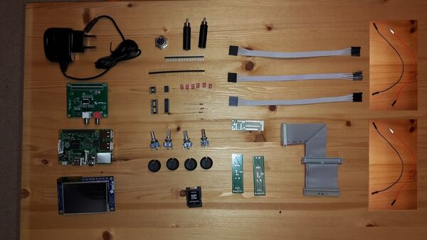
1.3.1 Bill of Material
Here is a list of the hardware components you will need to build the Zynthian device. I also provided links to my suppliers and the prices I paid for the components in February 2016. I bought everything from Germany, so all descriptions are in German and prices are in EUR. If you live in another country maybe you'll get things even cheaper.
| No | Shipper | Order no. | Description | Pieces | Price per piece [€] |
|---|---|---|---|---|---|
| 1 | http://www.reichelt.de | 1N 4148 | Planar Epitaxial Schaltdiode, DO35, 100V, 0,15A | 1 | 0,04 |
| 2 | http://www.reichelt.de | 6N 138 | OPTOKOPPLER | 1 | 0,58 |
| 3 | http://www.reichelt.de | RASPBERRY PI 2 | Raspberry Pi 2, 4x 900 MHz, 1 GB RAM | 1 | 37,50 |
| 4 | http://www.reichelt.de | RPI HB DAC+ RCA | HiFiBerry DAC+ RCA, Raspberry Pi Shield | 1 | 35,90 |
| 5 | http://www.reichelt.de | 1/4W 220 | Kohleschichtwiderstand 1/4W, 5%, 220 Ohm | 1 | 0,10 |
| 6 | http://www.reichelt.de | 1/4W 1,0K | Kohleschichtwiderstand 1/4W, 5%, 1,0 K-Ohm | 1 | 0,10 |
| 7 | http://www.reichelt.de | 1/4W 10K | Kohleschichtwiderstand 1/4W, 5%, 10 K-Ohm | 1 | 0,10 |
| 8 | http://www.reichelt.de | MKS-02 100N | WIMA Folienkondensator, Rm 2,5mm 100nF | 4 | 0,15 |
| 9 | http://www.reichelt.de | GS 18P | IC-Sockel, 18-polig, superflach, gedreht, vergold. | 1 | 0,32 |
| 10 | http://www.reichelt.de | GS 8P | IC-Sockel, 8-polig, superflach, gedreht, vergold. | 1 | 0,19 |
| 11 | http://www.reichelt.de | SL 2X25G 2,54 | 2x25pol.-Stiftleiste, gerade, RM 2,54 | 1 | 0,24 |
| 12 | http://www.reichelt.de | MAB 5S | DIN-Buchse, 5-polig | 1 | 0,24 |
| 13 (OPTIONAL) | http://www.reichelt.de | NTA 176 | 6,3 Mono-Klinken-Bu. auf Cinch-St. | 2 | 0,35 |
| 14 | http://www.reichelt.de | NT MUSB 2 SW | Micro-USB Steckernetzteil, schwarz, 5 V, 2 A | 1 | 8,40 |
| 15 | http://www.segor.de | MCP23008-E/P | MCP23008 8 port I2C-GPIO extender | 1 | 2,10 |
| 16 | http://www.amazon.de | Adafruit PiTFT 2.8" | Adafruit PiTFT Touchscreen Display, 2,8 Zoll, für Raspberry Pi Computer | 1 | 32,00 |
| 17 | http://www.ebay.de | 12mm Rotary Encoder Switch | Rotary Encoder with switch, 20 steps | 4 | 0,60 |
| 18 | http://www.ebay.de | Poti knob | Poti knob for Rotary encoder (Pos. 17) | 4 | 1,50 |
| 19 | http://blog.zynthian.org | Encoder PCB | PCB for encoders | 2 | 10,00 |
| 20 | http://blog.zynthian.org | 2in1 PCB | PCB for MIDI and GPIO extension | 1 | 10,00 |
| 21 | http://blog.zynthian.org | Main Bus Ribbon Cable | Raspberry Main Bus Ribbon Cable | 1 | 20,00 |
| 22 | http://blog.zynthian.org | Mini-ribbon cable | Mini-ribbon cable (6 pin female connector to 6 female jumper connectors | 3 | 3,00 |
| 23 | http://www.saturn.de | SD card | Samsung 32GB SD card | 1 | 14,00 |
| 24 | - | Short connector cables | Connector cables pin-female/pin-female for MIDI and external GPIO connector from 2in1 board | 4 | ??,?? |
| 25 | - | Multi-pin connector | 1x40pol.-Stiftleiste, gerade, RM 2,54 | 1 | ??,?? |
Notes:
- Pos. 19-22 were ordered directly from Zynthian.
- There is no case in this BoM - You can build your own or ask Zynthian.
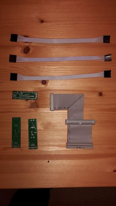
- Total price was 200,27 € (plus shipping).
1.4 Assembly and Soldering of the modules (PCBs)
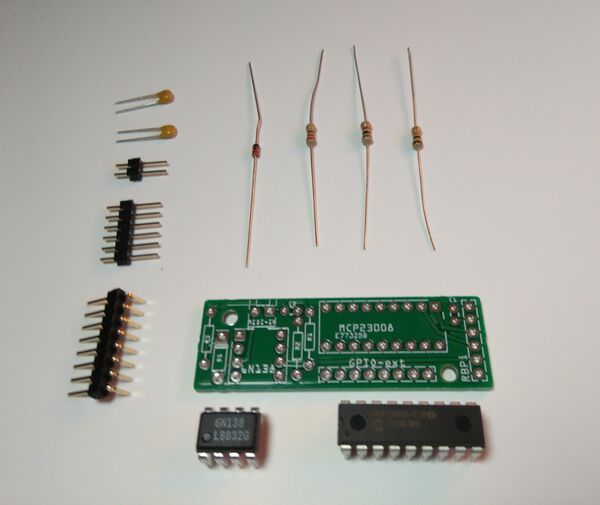
1.4.1 Step 1: 2in1 modules
1.4.1.1 You need:
- 1 * 2in1 PCB (Pos. 20)
- 2 * 100nF capacitor (Pos. 8)
- 1 * multi-pin 2 pins wide (part of pos. 24)
- 1 * multi-pin 6 pins wide (part of pos. 24)
- 1 * multi-pin 8 pins wide (part of pos. 24)
- 1 * resistor 10 kOhm (brown-black-orange-gold, pos. 7)
- 1 * resistor 1 kOhm (brown-black-red-gold, pos. 6)
- 1 * resistor 220 Ohm (red-red-black-gold, pos. 5)
- 1 * diode 1N4148 (pos. 1)
- 1 * IC socket 8 pins (pos. 10) => OPTIONAL! Not included in the Kit
- 1 * IC socket 18 pins (pos. 9) => OPTIONAL! Not included in the Kit
- 1 * IC 6N138 (pos. 2)
- 1 * IC MCP23008 (pos. 15)
- 2 * Connector cable pin-female/pin-female
- 1 * MIDI socket (DIN socket 5 pins)
- 1 * 2in1 PCB (pos. 20)
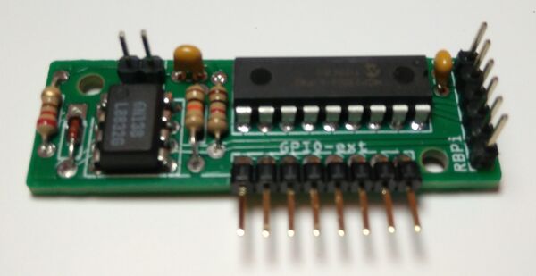
1.4.1.2 HowTo:
- Start with assembling the diode onto the PCB. Be careful to do this the right way - the small black (or white) stripe on one side of the diode must fit the same side of the white stripe on the PCB!
- After that, solder the resistors.
- Then assemble the ICs.Put attention to the orientation!!. If you prefer, you can use IC sockets (but do not fit the ICs yet, we will do this at the end of this task.)
- After that, solder the capacitors and the multi-pin-rows.
- If you used IC-sockets, now insert the ICs into the socket. Be careful to put them with the notch on the IC towards the hole of the white rectangle showing on the PCB!
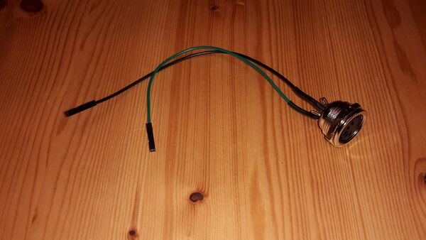
For the MIDI socket you have to cut off one side of the female/female cable and solder this side to the DIN-socket. Connect the cables to pin 5 (2nd from left) and pin 4 (2nd from right).
1.4.2 Step 2A: Controller Modules Dual (2 x dual encoder controllers)
Note: If you have the new Controller Single modules you must jump to the Step 2B.
1.4.2.1 You need (for one Controller Module):
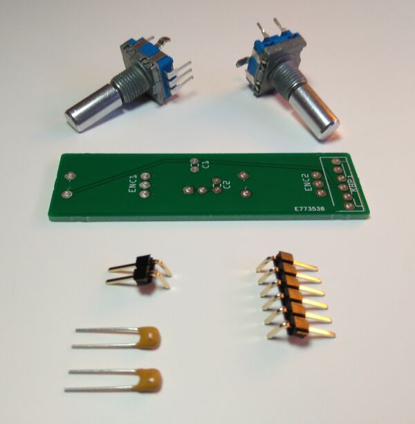
- 2 x rotary encoder with pushbutton (Pos. 17)
- 2 x 100nF capacitor (Pos. 8)
- 1 x multi-pin 6 pins angle (part of Pos. 24)
- 1 x multi-pin 2 pins angle (part of Pos. 24)
- 1 x controller module PCB (Pos. 19)
1.4.2.2 HowTo:
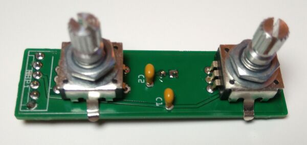
- The order of the following steps is not important: Solder the capacitors and the encoders to the board (on the upper side) - that's it.
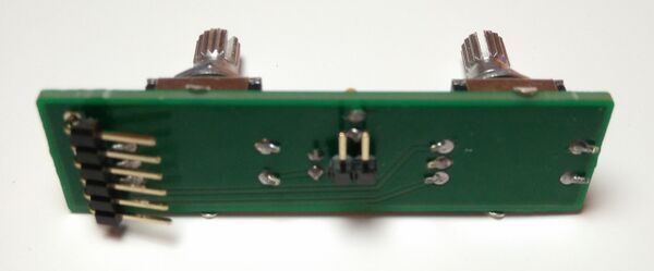
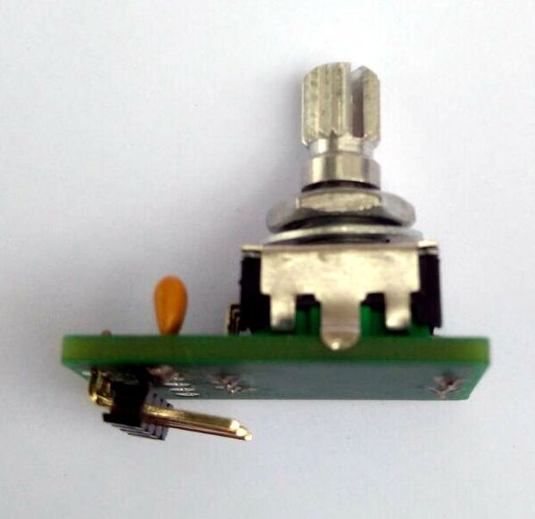
- Solder the 6-pin and 2-pin-rows. IMPORTANT! Due to the mounting of the encoders on a front panel, the pin-rows connectors must be soldered on the bottom of the PCB. The 6-pin-row must have its pins as showed in the photo (pin numbering will be 1..6 from the lower side of the PCB!). For optimal case mounting, the 2-pin-row should be soldered with different orientation in each module. One with right-orientation and the other one with left-orientation.
- You have to do this twice - you need two encoder boards ;-)
Note: Mount the pin row at the bottom of the PCB. Look the photos!!! ;-)
1.4.3 Step 2B: Controller Modules Single (4 x single encoder controllers)
Note: If you have the old Controller modules, with 2 rotary encoders each, you must read the Step 2A.
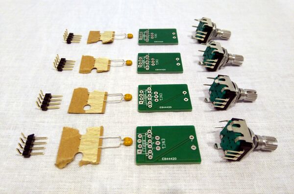
1.4.3.1 You need (for one Controller Single Module):
- 1 x rotary encoder with pushbutton (Pos. 17)
- 1 x 100nF capacitor (Pos. 8)
- 1 x multi-pin 4 pins angle
- 1 x controller single PCB
1.4.3.2 HowTo:
- The order of the following steps is not important: Solder the capacitor in the C1 position (right side) and the encoder to the board (on the upper side) - that's it.
- Solder the 4-pin-row. IMPORTANT! Due to the mounting of the encoders on a front panel, the pin-row connector must be soldered on the bottom of the PCB. The 4-pin-row must have its pins as showed in the photo (pin numbering will be 1..4 from the lower side of the PCB!).
- You have to do this 4 times - you need 4 encoder boards ;-)
1.4.4 Step 3: Pin row on the Hifiberry
1.4.4.1 You need:
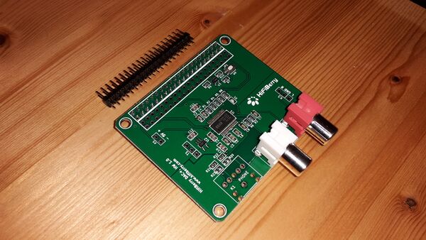
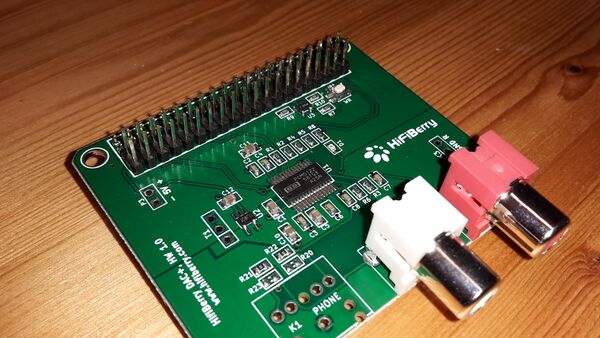
- 1 * HiFiBerry DAC+ RCA, Raspberry Pi Shield (Pos. 4)
- 1 * 2x25pol.-Stiftleiste, gerade, RM 2,54 (Pos. 11)
1.4.4.2 HowTo:
- For this part you should take some time. Damaging the Hifiberry because you are in a hurry won't make your day!
- First of all: cut the 2*25 pin-row to 2*20 pin (perhaps with a cutter).
- Place the pin row on the Hifiberry and start soldering on the back of the Hifiberry. I always solder pins which are not close together to avoid hot spots. You take a few pauses in between to have the PCB cool down. Never let the PCB get too hot, because otherwise solder on the components' side may melt and components may fall off or become shorted.
1.4.5 Checking everything
Congratulations - you're halfway through!
Now you should double-check everything you soldered:
- Were the components soldered in their correct orientation (e.g. polarity, pin layout)?
- Are there any solder bridges between pins? Remove them!
- Is the diode on the 2in1-PCB correctly oriented?
- Are the ICs pointing in the right direction?
- Are all pins of the ICs in their sockets?
Hint:
- Use a magnifying glass and bright light to check.
1.5 Connecting the cables
1.5.1 You need:
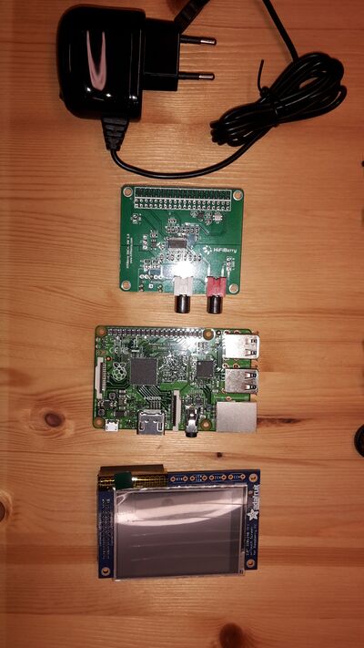
- 1 * Raspberry Pi 2 (Pos. 3)
- 1 * HiFiBerry DAC+ RCA (Pos. 4)
- 1 * Adafruit PiTFT Touchscreen Display, 2,8 Zoll (Pos. 16)
- 1 * Raspberry Main Bus Ribbon Cable (Pos. 21)
- 3 * Mini-ribbon cable (6 pin female connector to 6 female jumper connectors(Pos. 22)
- 2 * Connector cables pin-female/pin-female (Pos. 24)
1.5.2 Raspberry Pi and Hifiberry DAC+
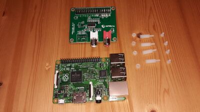
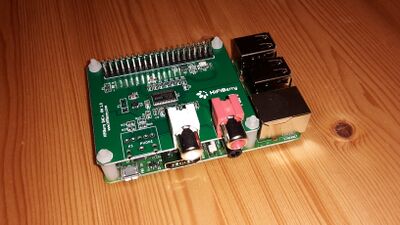
Put the Hifiberry DAC+ onto the Raspberry Pi's GPIO header. With the Hifiberry you get 4 distance pieces and 4 screws (all plastic). Put them together as shown in the following picture.
1.5.3 TFT
Time for connecting the main ribbon-cable using the (female) 40-pin-connector to the Hifiberry. At the other end of the cable there is a (female) 26-pin-connector. This one must be connected to the PiTFT. If you have a clone PiTFT which has no suitable port you have to solder one in or use a gender changer. The original PiTFT has both male and female connectors.
1.5.4 2in1
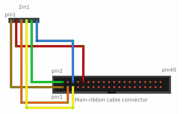
The 2in1-PCB must be connected using one of the mini ribbon cables. The 6-pin connector must be located towards the PCB. Pin 1 is on the bottom left (component side up). On the other end of the cable there are 1-pin female connectors. They must be connected to the following pins on the (male) 40-pin-conenctor in the middle of the main ribbon cable.
| Wire no. | Function | GPIO no. | Pin on Raspi no. |
|---|---|---|---|
| 1 | Vdc 3.3V | 3.3V | 1 |
| 2 | RxD | RxD | 10 |
| 3 | I2C SDA1 | 08 | 3 |
| 4 | I2C SCL1 | 09 | 5 |
| 5 | Vdc 5V | 5V | 2/4 |
| 6 | GND | GND | 6/9 |
Next connect the DIN socket (MIDI) to the 2in1-PCB. The connector on the PCB is the 2-pin one located in the upper right corner of the PCB.
| Wire no. | Function | MIDI-IN pin no. |
|---|---|---|
| 1 | MIDI-IN | 2 (MIDI connector: 2nd from left) |
| 2 | MIDI-IN | 4 (MIDI connector: 2nd from right) |
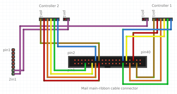
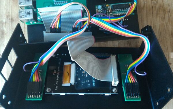
1.5.5 Controller Dual Module x 2 (2 rotary encoders each PCB)
This step is a bit tricky. Remember that, if you follow the instructions before, you have soldered the pin-rows in the bottom side of PCBs, so numbering is reversed when looking from bottom. You can use a little trick: if you rotate the PCB 180º, then numbering is "left to right" again ;-)
So you should look at your controller modules from bottom side and with the pin-row on the top of PCB!
PHOTO NEEDED HERE!!
Note: Some encoders have reversed pin ordering, so, if you buy the encoders by yourself, perhaps you have to change A and B pins.
1.5.5.1 Controller 1
| Wire no. | Function | GPIO no. | Pin on Raspi no. |
|---|---|---|---|
| 1 | Enc1-B | 25 | 37 |
| 2 | Enc1-A | 27 | 36 |
| 3 | Enc1-SW | 23 | 33 |
| 4 | Enc2-B | 26 | 32 |
| 5 | Enc2-A | 21 | 29 |
| 6 | GND | GND | 30 |
| Wire no. | Function | Pin on 2in1 |
|---|---|---|
| 1 | GND | - |
| 2 | Enc2-SW | X07 |
1.5.5.2 Controller 2
| Wire no. | Function | GPIO no. | Pin on Raspi no. |
|---|---|---|---|
| 1 | Enc1-B | 04 | 16 |
| 2 | Enc1-A | 03 | 15 |
| 3 | Enc1-SW | 02 | 13 |
| 4 | Enc2-B | 00 | 11 |
| 5 | Enc2-A | 07 | 07 |
| 6 | GND | GND | 14 |
| Wire no. | Function | Pin on 2in1 |
|---|---|---|
| 1 | GND | - |
| 2 | Enc2-SW | X08 |
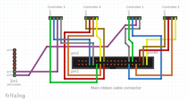
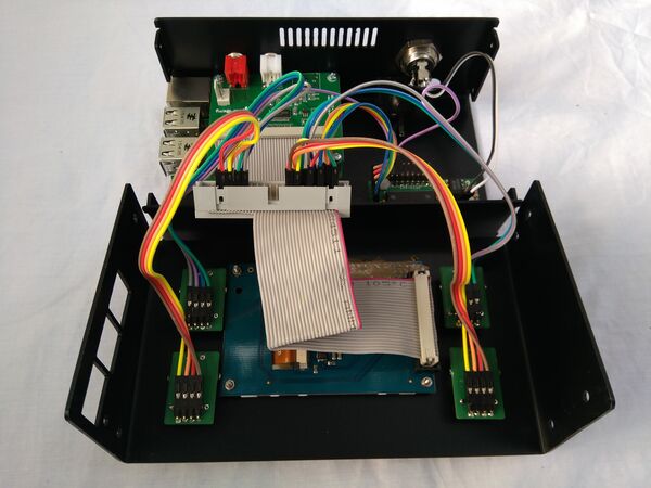
1.5.6 Controller Single Module x 4 (one single rotary encoder each PCB)
This step is a bit tricky. Remember that, if you followed the instructions before, you have soldered the pin-rows in the bottom side of PCBs, so numbering is reversed when looking from bottom. You can use a little trick: if you rotate the PCB 180º, then numbering is "left to right" again ;-)
So you should look at your controller modules from bottom side and with the pin-row on the top of PCB!
PHOTO NEEDED HERE!!
Note: Some encoders have reversed pin ordering, so, if you buy the encoders by yourself, perhaps you have to change A and B pins.
Warning: In this photo the controller modules wiring is reversed (1 by 2, 3 by 4). I will change it ASAP ;-)
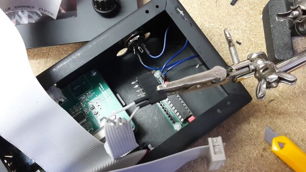
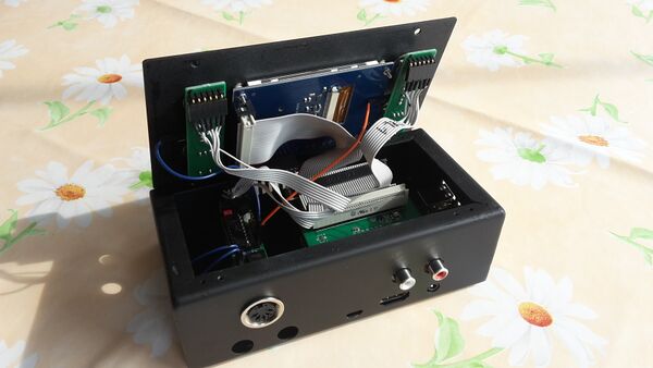
1.5.7 Alternative cabling
An alternative cabling can be done with an old floppy ribbon cable. You won't need the 3 minni-ribbon-connectors (6-pin) but have to solder 6-pin connectors on the floppy cable (40-pin-ribbon). The cabling plan is the same as above.
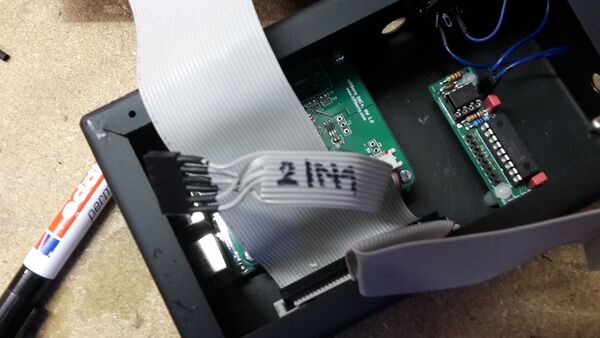 6-pin connector for the 2IN1 is ready
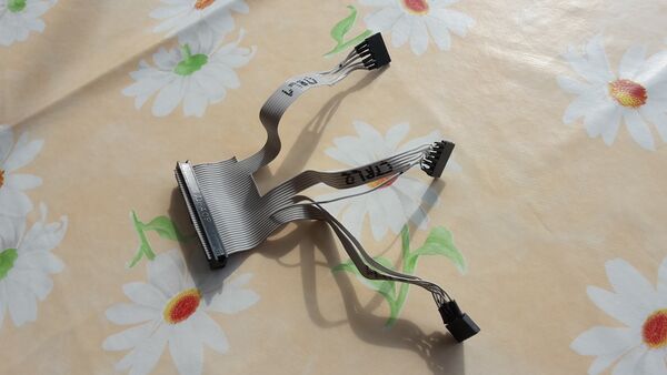 The complete cable ready for installation
1.6 Creating the SD
1.6.1 Getting the Image
You can get the last SD image here:
1.6.2 Writing the image to the SD card
If you successfully downloaded the whole image, you can now write it to an SD-card.
You need a minimum size of 16GB, better 32GB SDcard to allow for more instruments and sample-sets in future.
Use Etcher https://etcher.io/ (free software works on Mac, Windows or Linux)
Or do it manually: Depending on your OS you have to choose how to create the SD-card. There is a really good manual for this at | https://www.raspberrypi.org/documentation/installation/installing-images/.
