Difference between revisions of "Adding Extra I/O with the Zynaptik Module"
| Line 43: | Line 43: | ||
=== Configuring Zynaptik Customizable Switches === | === Configuring Zynaptik Customizable Switches === | ||
| − | Simply add the switches pins to the list. Zynaptik MCP23017 pins start at 200. You don't need to add all the 16 | + | Simply add the switches pins to the list. Zynaptik MCP23017 pins start at 200. You don't need to add all the 16 available switches. If you only want to use 2, simply add "200,201". |
After saving, you will see that the extra custom switches are available for configuration. | After saving, you will see that the extra custom switches are available for configuration. | ||
Revision as of 08:25, 21 August 2020
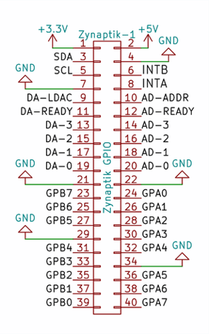
The Zynaptik module allows to solder on it 3 extra submodules and a 40 pin header for interfacing them:
+ Secondary MCP23017 (Digital I/O): It uses I2C address 0x21 and the 2 interrupt lines are connected to the RBPi GPIO. INTA to GPIO27 (pin 36) and INTB to GPIO25 (pin 37). The digital I/O are labelled as GPAx & GPBx on the Zynaptik's header schematic.
You can use it for adding up to 16 extra switches to your zynthian.
+ ADS1115 (MOD-1 Analog Input): It uses I2C address 0x48 by default. The 4 analog input pins are labelled as ADx on the Zynaptik's header schematic.
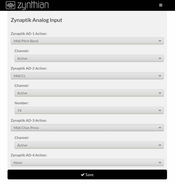
You can assign the Analog Inputs to MIDI events like Pitch-Bending, CC or ChanPress. This can be used for connecting CV-IN or for controlling sound engine parameters using analog sensors.
+ MCP4728 (MOD-2 Analog Output): It uses I2C address 0x60 by default. The 4 analog output pins are labelled as DAx on the Zynaptik's header schematic.
It's currently unimplemented. The highest honor is deserved to the brave who kill this dragon ...
1 Configuring the Zynaptik Module from the Webconf
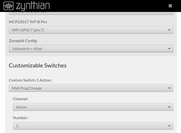
First, you should choose the right configuration for your zynaptik module depending on the extra modules you have soldered on it:
- 16xSWITCH => Only MCP23017, use the 16 GPIOs as customizable switches
- 4xAD => Only ADS1115 (use the 4 ADs for Analog Input, obvious)
- 16xSWITCH + 4xAD => MCP23017 + ADS1115, use the 16 GPIOs as customizable switches
After saving, you may want to configure your switches and/or analog inputs.
2 Configuring Zynaptik Customizable Switches
Simply add the switches pins to the list. Zynaptik MCP23017 pins start at 200. You don't need to add all the 16 available switches. If you only want to use 2, simply add "200,201". After saving, you will see that the extra custom switches are available for configuration.
3 Configuring Zynaptik Analog Input
Simply configure your analog inputs from the webconf's wiring section in the same way you configure your custom switches.


