Difference between revisions of "Adding Extra I/O with the Zynaptik Module"
| Line 36: | Line 36: | ||
* '''16xSWITCH''' => Only MCP23017, use the 16 GPIOs as customizable switches | * '''16xSWITCH''' => Only MCP23017, use the 16 GPIOs as customizable switches | ||
| − | |||
* '''4xAD''' => Only ADS1115 (use the 4 ADs for Analog Input, obvious) | * '''4xAD''' => Only ADS1115 (use the 4 ADs for Analog Input, obvious) | ||
* '''16xSWITCH + 4xAD''' => MCP23017 + ADS1115, use the 16 GPIOs as customizable switches | * '''16xSWITCH + 4xAD''' => MCP23017 + ADS1115, use the 16 GPIOs as customizable switches | ||
| − | |||
After saving, you may want to configure your switches and/or analog inputs. | After saving, you may want to configure your switches and/or analog inputs. | ||
Revision as of 08:24, 21 August 2020
The Zynaptik module allows to solder on it 3 extra submodules and a 40 pin header for interfacing them:
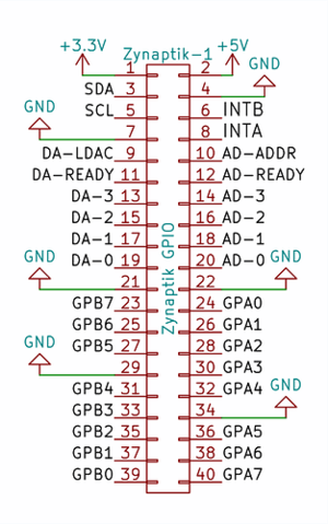
+ Secondary MCP23017 (Digital I/O): It uses I2C address 0x21 and the 2 interrupt lines are connected to the RBPi GPIO. INTA to GPIO27 (pin 36) and INTB to GPIO25 (pin 37). The digital I/O are labelled as GPAx & GPBx on the Zynaptik's header schematic.
You can use it for adding up to 16 extra switches to your zynthian.
+ ADS1115 (MOD-1 Analog Input): It uses I2C address 0x48 by default. The 4 analog input pins are labelled as ADx on the Zynaptik's header schematic.
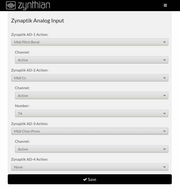
You can assign the Analog Inputs to MIDI events like Pitch-Bending, CC or ChanPress. This can be used for connecting CV-IN or for controlling sound engine parameters using analog sensors.
+ MCP4728 (MOD-2 Analog Output): It uses I2C address 0x60 by default. The 4 analog output pins are labelled as DAx on the Zynaptik's header schematic.
It's currently unimplemented. The highest honor is deserved to the brave who kill this dragon ...
1 Configuring the Zynaptik Module from the Webconf
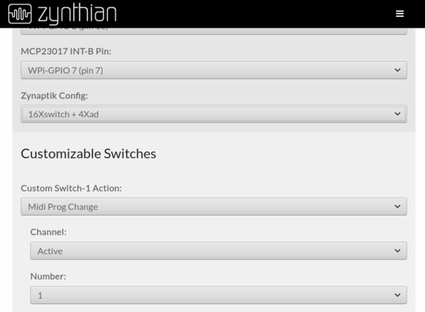
First, you should choose the right configuration for your zynaptik module depending on the extra modules you have soldered on it:
- 16xSWITCH => Only MCP23017, use the 16 GPIOs as customizable switches
- 4xAD => Only ADS1115 (use the 4 ADs for Analog Input, obvious)
- 16xSWITCH + 4xAD => MCP23017 + ADS1115, use the 16 GPIOs as customizable switches
After saving, you may want to configure your switches and/or analog inputs.
2 Configuring Zynaptik Customizable Switches
Simply add the switches pins to the list. Zynaptik MCP23017 pins start at 200. You don't need to add all the 16/8 available switches. If you only want to use 2, simply add "200,201". After saving, you will see that the extra custom switches are available for configuration.
3 Configuring Zynaptik Analog Input
Simply configure your analog inputs from the webconf's wiring section in the same way you configure your custom switches.


