Difference between revisions of "Adding Extra Switches"
m |
|||
| (22 intermediate revisions by 2 users not shown) | |||
| Line 1: | Line 1: | ||
| − | The All-In-One circuit can be | + | ==Using All-In-One module or Zynscreen display (MCP23017)== |
| + | |||
| + | The All-In-One circuit (or the Zynscreen display) can easily be modified by adding up to 4 extra switches which can be used for a panic button, a sustain pedal, or other MIDI-CC switches (very useful for SooperLooper!). | ||
The unused pins in the MCP23017 are: | The unused pins in the MCP23017 are: | ||
| − | pin 27 (GPA6) | + | * pin 27 (GPA6) |
| − | pin 28 (GPA7) | + | * pin 28 (GPA7) |
| − | pin 7 (GPB6) | + | * pin 7 (GPB6) |
| − | pin 8 (GPB7) | + | * pin 8 (GPB7) |
| − | The first 2 are bound to INTA and the other 2 to INTB. | + | |
| + | The first 2 are bound to INTA and the other 2 to INTB | ||
| + | |||
| + | If you have a recent version of the All-In-One circuit (or a Zynscreen display), it includes an extra row-pin connector (SW1) that allows to easily use these extra GPIO ports. If you don't, you have to solder your wires directly to the MCP23107 pins. | ||
| + | This is the pin assignment for the row-pin connector (SW1): | ||
| + | |||
| + | * pin 1 => GND | ||
| + | * pin 2 => WiringPi GPIO 106 | ||
| + | * pin 3 => WiringPi GPIO 107 | ||
| + | * pin 4 => WiringPi GPIO 114 | ||
| + | * pin 5 => WiringPi GPIO 115 | ||
| + | |||
| + | You can check the All-In-One schematic [http://wiki.zynthian.org/images/4/44/Zynthian_allinone.sch.svg here] | ||
| + | |||
| + | [[File:pcb_all-in-one_v2.1.jpg|700px]] | ||
| + | |||
| + | [[File:module_all-in-one_v2.1.jpg|700px]] | ||
| + | |||
| + | You can check the Zynscreen schematic [http://wiki.zynthian.org/images/4/40/ZynScreen_v1.3.svg here] | ||
| + | |||
| + | [[File:Zynscreen sw1.jpg|700px]] | ||
| + | |||
| + | So, if you have a recent version of All-In-One circuit (or a Zynscreen display), you can follow these simple steps to add your custom switches: | ||
| + | |||
| + | * Update your zynthian | ||
| + | * Solder the 5 row-pin connector to your All-In-One circuit (or Zynscreen display) (SW1) | ||
| + | * Connect some kind of switch between pins 2-5 and pin 1 (GND). The switches are normally open, closing to pin 1 (GND). | ||
| + | * From the webconf tool go to the hardware menu => wiring section: | ||
| + | ** Select MCP23017_EXTRA as wiring layout (MCP23017_ZYNSCREEN if you have the Zynscreen display). This will set your ZYNTHIAN_WIRING_SWITCHES to “100,103,108,111,106,107,114,115” | ||
| + | ** Configure the desired actions (advanced options). The UI active layer’s MIDI channel will be used for MIDI actions. | ||
| + | |||
| + | You can read more about this subject here: | ||
| + | |||
| + | * https://discourse.zynthian.org/t/extra-switches-sw1-sustain-pedal-panic-button-etc/1843 | ||
| + | * https://discourse.zynthian.org/t/extra-switches-now-customizable-from-webconf/2765 | ||
| + | |||
| + | ===Example 1: Adding a "Panic Button" to an official v2 zynthian=== | ||
| + | |||
| + | You could add a panic button to your zynthian box. Simply make a hole, install the switch-button, and connect it to SW-1's pins 1 & 2. | ||
| + | |||
| + | [[File:Zynthian v2 panic switch.jpeg|700px]] | ||
| + | |||
| + | Next, configure the actions in the webconf tool as follow: | ||
| + | |||
| + | * Type: Ui Action | ||
| + | * Short push: All Note Off | ||
| + | * Bold push: All Off (All Notes Off + All Sounds Off) | ||
| + | * Long push: Reboot | ||
| + | |||
| + | ===Example 2: External 3 switches pedal + sustain pedal=== | ||
| + | |||
| + | Our dear friend, @wolfpaw98, has developed this amazing pedal set. He uses a MIDI connector (DIN-5) to make the 5 pins from the case accessible. The main pedal is connected to the DIN-5, and a Jack-mono connector is used to connect the sustain to the main pedal. | ||
| − | + | [[File:Zynthian pedals 01.jpeg|700px]] | |
| − | + | [[File:Zynthian pedals 02.jpeg|700px]] | |
| − | + | [[File:Zynthian pedals 03.jpeg|700px]] | |
| − | + | [[File:Zynthian pedals 04.jpeg|700px]] | |
| − | + | You can read more about this subject here: | |
| − | * | + | * https://discourse.zynthian.org/t/funny-pedalboxes-for-zynthian-using-extra-switches/3331 |
| − | + | ==Zynthian without encoders using legacy 2in1 module for Extra Switches== | |
| − | + | You can configure a zynthian without controllers (encoders+switches) for using an ancient 2in1 module to get up to 4 extra switches that you can bind to CUIA or MIDI actions. | |
| − | + | This is the wiring layout configuration you have to setup in the webconf tool: | |
| − | + | [[File:Webconf_noencoders_2in1_extra_switches.png|700px]] | |
| − | |||
| − | |||
| − | |||
| − | |||
| − | + | {{NoteBox|As the 2in1 module doesn't use the MCP23008's INTA pin, switches are detected by polling, so i strongly recommend to only configure the pins you are actually using.}} | |
| − | + | ==Using free RBPi GPIO pins as Extra Switches== | |
| − | |||
| − | |||
| − | |||
| − | |||
| − | |||
| − | + | In the same way, you can configure any free GPIO pins in the Raspberry Pi as extra switches. You only have to configure the "Switches Pins" in the webconf tool. | |
Latest revision as of 14:40, 13 January 2020
1 Using All-In-One module or Zynscreen display (MCP23017)
The All-In-One circuit (or the Zynscreen display) can easily be modified by adding up to 4 extra switches which can be used for a panic button, a sustain pedal, or other MIDI-CC switches (very useful for SooperLooper!).
The unused pins in the MCP23017 are:
- pin 27 (GPA6)
- pin 28 (GPA7)
- pin 7 (GPB6)
- pin 8 (GPB7)
The first 2 are bound to INTA and the other 2 to INTB
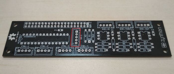
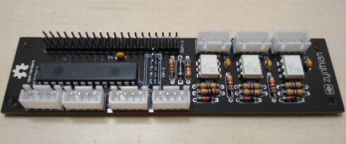
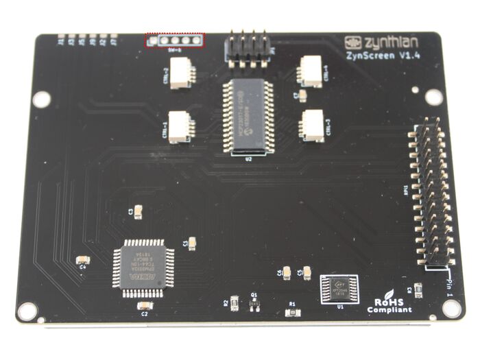
If you have a recent version of the All-In-One circuit (or a Zynscreen display), it includes an extra row-pin connector (SW1) that allows to easily use these extra GPIO ports. If you don't, you have to solder your wires directly to the MCP23107 pins. This is the pin assignment for the row-pin connector (SW1):
- pin 1 => GND
- pin 2 => WiringPi GPIO 106
- pin 3 => WiringPi GPIO 107
- pin 4 => WiringPi GPIO 114
- pin 5 => WiringPi GPIO 115
You can check the All-In-One schematic here
You can check the Zynscreen schematic here
So, if you have a recent version of All-In-One circuit (or a Zynscreen display), you can follow these simple steps to add your custom switches:
- Update your zynthian
- Solder the 5 row-pin connector to your All-In-One circuit (or Zynscreen display) (SW1)
- Connect some kind of switch between pins 2-5 and pin 1 (GND). The switches are normally open, closing to pin 1 (GND).
- From the webconf tool go to the hardware menu => wiring section:
- Select MCP23017_EXTRA as wiring layout (MCP23017_ZYNSCREEN if you have the Zynscreen display). This will set your ZYNTHIAN_WIRING_SWITCHES to “100,103,108,111,106,107,114,115”
- Configure the desired actions (advanced options). The UI active layer’s MIDI channel will be used for MIDI actions.
You can read more about this subject here:
- https://discourse.zynthian.org/t/extra-switches-sw1-sustain-pedal-panic-button-etc/1843
- https://discourse.zynthian.org/t/extra-switches-now-customizable-from-webconf/2765
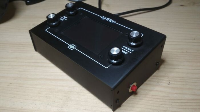
1.1 Example 1: Adding a "Panic Button" to an official v2 zynthian
You could add a panic button to your zynthian box. Simply make a hole, install the switch-button, and connect it to SW-1's pins 1 & 2.
Next, configure the actions in the webconf tool as follow:
- Type: Ui Action
- Short push: All Note Off
- Bold push: All Off (All Notes Off + All Sounds Off)
- Long push: Reboot
1.2 Example 2: External 3 switches pedal + sustain pedal
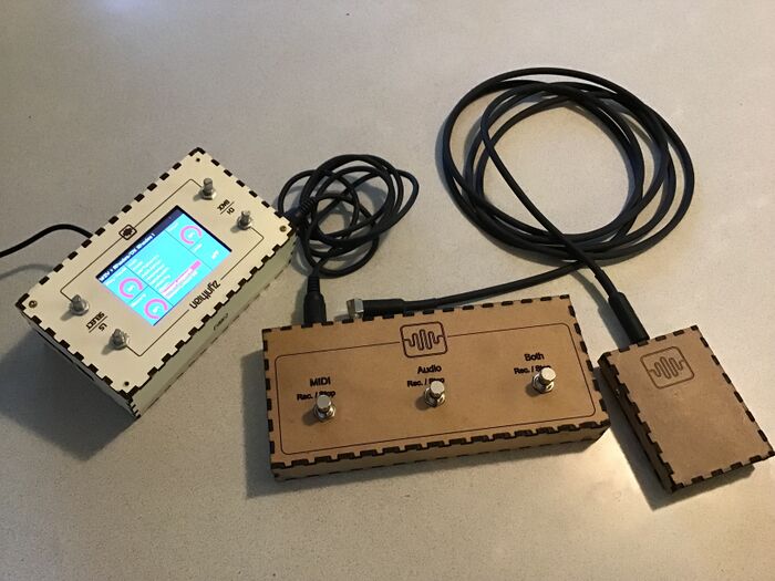
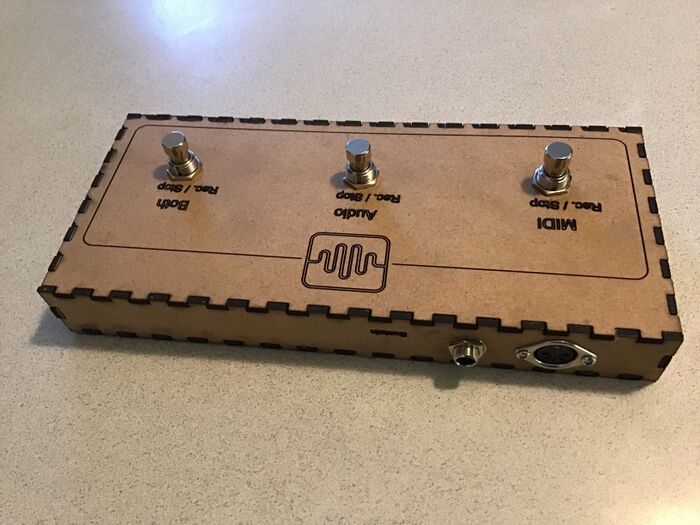
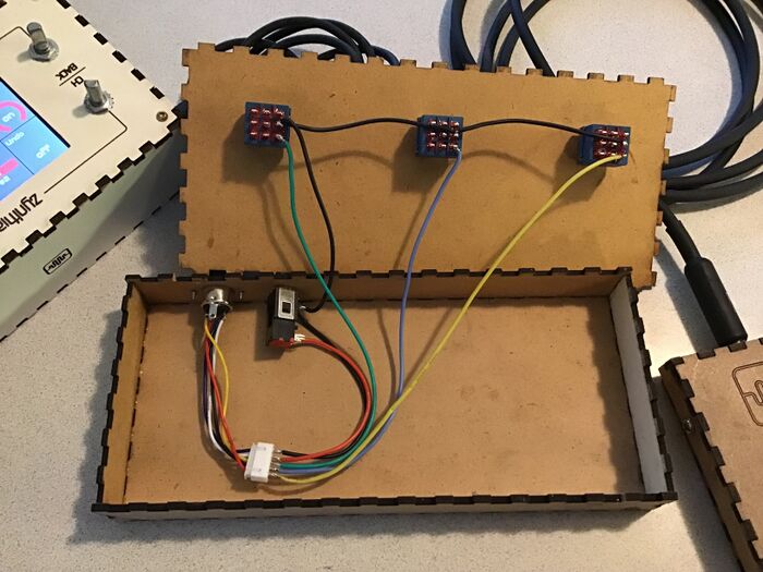
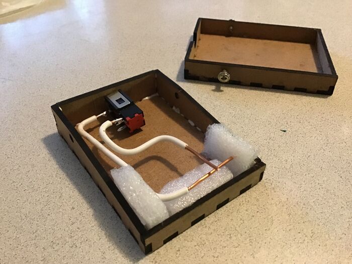
Our dear friend, @wolfpaw98, has developed this amazing pedal set. He uses a MIDI connector (DIN-5) to make the 5 pins from the case accessible. The main pedal is connected to the DIN-5, and a Jack-mono connector is used to connect the sustain to the main pedal.
You can read more about this subject here:
2 Zynthian without encoders using legacy 2in1 module for Extra Switches
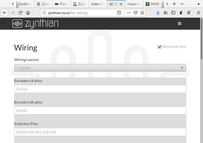
You can configure a zynthian without controllers (encoders+switches) for using an ancient 2in1 module to get up to 4 extra switches that you can bind to CUIA or MIDI actions.
This is the wiring layout configuration you have to setup in the webconf tool:
Note:
As the 2in1 module doesn't use the MCP23008's INTA pin, switches are detected by polling, so i strongly recommend to only configure the pins you are actually using.
3 Using free RBPi GPIO pins as Extra Switches
In the same way, you can configure any free GPIO pins in the Raspberry Pi as extra switches. You only have to configure the "Switches Pins" in the webconf tool.
